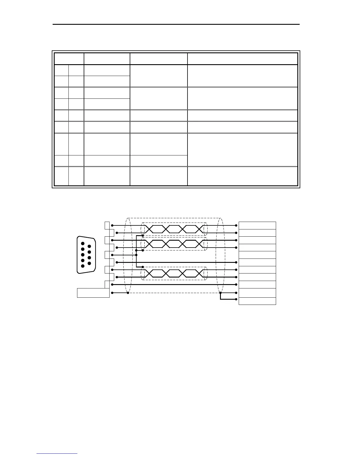
5.2 Pin configuration Resolver [X2A]
Pin No. Denomination Value Specification
1
S2 3,5V
RMS
/ 5-10kHz
R
i
> 5kΩ
SINE trace signal, differential
6 S4
2
S1 3,5V
RMS
/ 5-10kHz
R
i
> 5kΩ
COSINE trace signal, differential
7 S3
3
AGND 0V Shield for signal pairs (inner shield)
8 MT- GND Reference potential temperature sensor
4
R1 7V
RMS
/ 5-10kHz
I
A
≤ 150mA
RMS
Carrier signal for resolver
9 R2 GND
5
MT+ +3,3V / Ri=2kΩ
Motor temperature sensor, normally closed
contact, PTC, NTC, KTY
The outer shield is always connected to PE (connector housing) on the controller side.
The three inner shields are connected on one side of the servo positioning controller
ARS 2300 FS to PIN 3 of [X2A].
5.3 Pin configuration Encoder [X2B]
At the 15-pole D-Sub connection [X2B], motors with encoder can be feedback. The possible
incremental encoders for the encoder connection are divided into several groups.
Standard incremental encoders with and without commutation signals.
Stegmann encoders with HIPERFACE®: single- and multi-turn encoders with analog incremental
signals.
Encoders with EnDat interface.
Serial encoders with and without analog signal