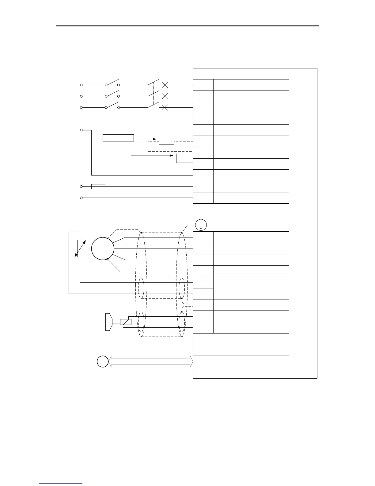
Resolver / Encoder
SM
E
24V / 2A
for the
holding brake
Power Supply [X9]
Motor feedback [X2A] / [X2B]
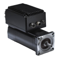
ARS 2302 FS, 2305 FS and 2310 FS
24V Supply
Motor feedback
T
Permanent-magnet
synchronous maschine
Ground conductor from motor
L 3
PE
+24V
0V
F1
External brake
resistor
Bridge circuit for
internal brake resistor
alternative !
L 2
ZK+ Pos. DC bus voltage
ZK- Neg. DC bus voltage
BR-INT
Connection of internal brake
resistor
BR-CH
Brake chopper connection for
internal/external brake resistor
PE
Connection ground conductor from
mains
+24V
Supply for control part (1A) and
holding brake (2A)
GND24V Reference potential supply
Mains phase 2
L 3
Motor [X6]
U
Motor phase 2
W Motor phase 3
PE Ground connection from motor
MT+
Motor temperature sensor, normally
closed contact, PTC, KTY...
MT-
PE
Cable shield from holding brake
and motor temperature sensor
BR+
BR-
Holding brake, signal level
depentdent on switch status,
high side / low side switch
Motor phase 1
V
L 1
Mains phase 1
Mains phase 3
230VAC ... 480 VAC
+/- 10%
L 2
L 1
BR-EXT
Connection of external brake
resistor
main fuse
Figure 5: Connection to power supply [X9] and motor [X6]
The servo positioning controller ARS 2300 FS is connected to the supply voltage, the motor, the brake
resistor and the holding brakes as shown in Figure 5. The operation of the servo positioning controller
ARS 2300 FS requires a 24V supply source for the electronics, which is connected to the terminals
+24V and GND24V. The connection to the supply for the power output stage is either made to
terminals L1, L2 and L3 for AC supply or to ZK+ and ZK- for DC supply.