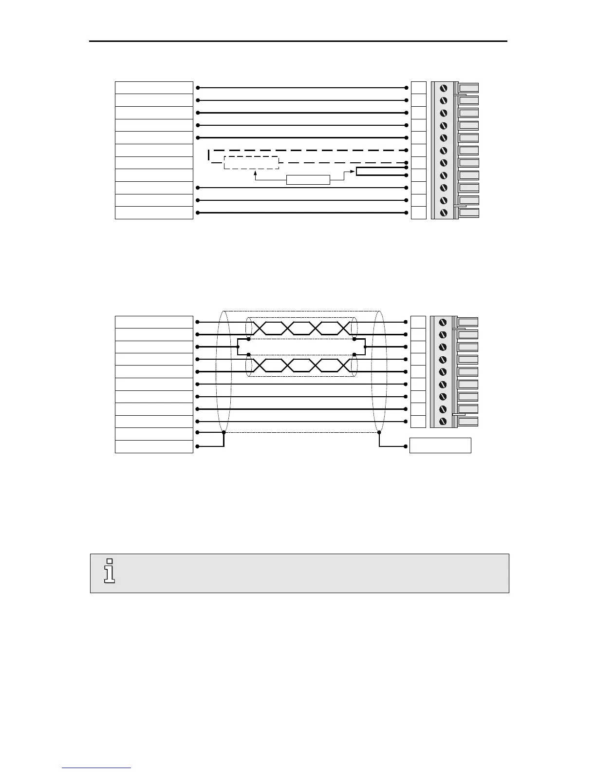
The motor is connected to the terminals U,V,W via motor cable to [X6].
The motor temperature sensore is connected to terminals MT+ and MT-, if it is lead into one cable
together with the motor phases. If a temperature sensor (e.g. KTY81) is used in the motor, it is
connected via the encoder cable to [X2A] or [X2B].
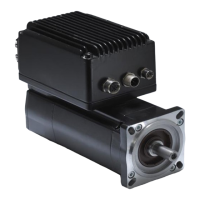
Connect the inner shields to PIN 3; maximum length 40 mm.
Length of unshielded cores maximum 35 mm.
Connect total shield on controller side flat to PE terminal; maximum length 40 mm. Use shield
clamp (SK14) or connect to PE screw terminal
Connect total shield on motor side flat to connector or motor housing; maximum length 40 mm.
The cable shield of the motor cable must also be connected to the controller housing
(PE screw terminal).
The connection of the shaft encoder via the D-Sub connector to [X2A] / [X2B] is roughly shown in
Figure 5.
The servo positioning controller ARS 2300 FS must be connected to ground with its PE connection.
The ARS 2300 FS must be completely wired first (excepted [X2B], see information mark below). Only
then may the operating voltages for the DC bus and the electronics supply be switched on. In the case
of inversed wiring of the operating voltage connections, excessive operating voltage or in the case of
confusing the connections for operating voltage and motor the servo positioning controller will be
damaged.