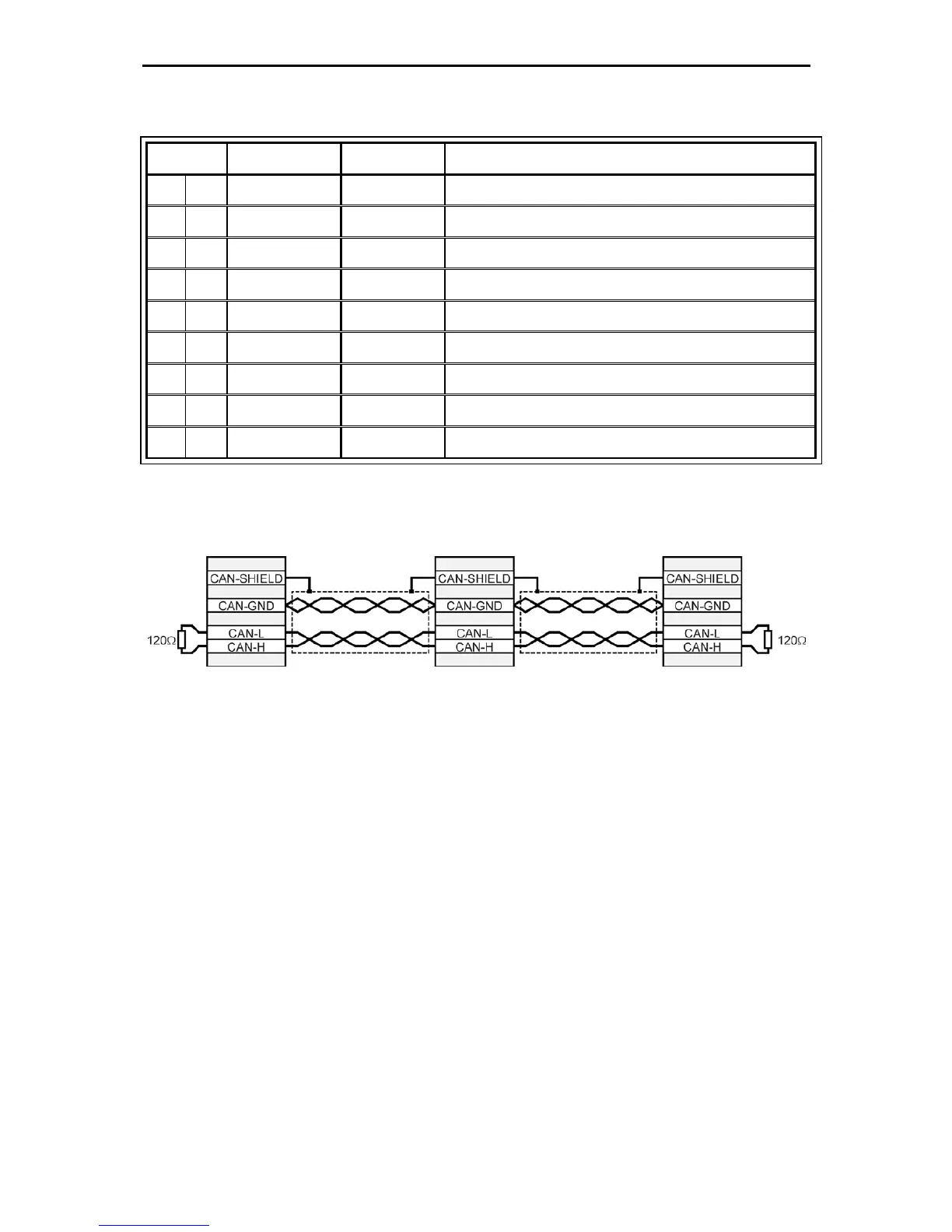
5.4 Pin configuration CAN [X4]
Pin No. Denomination Value Specification
1 - - Not occupied
6 GND 0V CAN-GND, galvanically connected to GND in controller
2 CANL *) CAN-Low signal line
7 CANH *) CAN-High signal line
3 GND 0V See Pin no. 6
8 - - Not occupied
4 - - Not occupied
9 - - Not occupied
5 Cable shield PE Connection for cable shield
*) Externally connectable termination resistor (“CAN TERM” switch terminating resistor 120Ω
required on both ends of the bus).