EasyManua.ls Logo

Metronix ARS 2302 - Page 28

Default Icon
39 pages
Print Icon
To Next Page IconTo Next Page
To Previous Page IconTo Previous Page
Loading...
Electrical installation Page 28
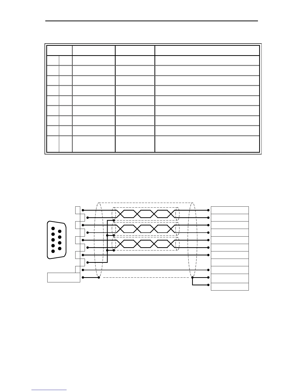
5.8 Pin configuration Incremental Encoder Output [X11]
Pin No. Denomination Value Specification
1 A 5V / R
A
66 *) Incremental encoder signal A
6 #A 5V / R
A
66 *) Incremental encoder signal #A
2 B 5V / R
A
66 *) Incremental encoder signal B
7 #B 5V / R
A
66 *) Incremental encoder signal #B
3 N 5V / R
A
66 *) Incremental encoder index pulse N
8 #N 5V / R
A
66 *) Incremental encoder index pulse #N
4 GND - Reference GND for encoder
9 GND - Shield for connection cable
5 VCC +5V ±5% 100mA
Auxiliary supply, to be loaded with maximal 100mA,
short-circuit-proof
*) The value for R
A
is the differential output resistance
2
3
4
5
6
7
8
1
9
Connector
housing
1
5
9
6
#B
B
N
A
#N
GND
VCC
#A
Incremental encoder
output
D-SUB
connector at
X11
Male
Cable shield
(optional)
Connector housing

Related product manuals