16
5 Pull the POWER SWITCH up to turn the Transmitter ON.
6 Trace the signal with the Receiver; see Section 4.4 for Receiver Operating Instructions.
4.2 Transmitter – Inductive Coupling with a Metroclamp
Use this method if Direct Connection is not possible, but you can position a Metroclamp around the conductor
you want to trace. The Inductive Coupling method uses a Metroclamp to induce a signal onto the conductor when
direct metallic contact is not possible. The clamp is placed around the target conductor. The Transmitter then
induces a signal through the clamp.
When using the Metroclamp, the conductor must be well grounded at both ends. When tracing lines that have
insulators, the insulators should be bypassed, using the supplied jumper cables. Bonding and grounding at
termination id often “standard practice” in industries that use cable, but do not assume this to be the case.
1 With the Transmitter OFF, plug the Metroclamp able into the DIRECT/4820 Clamp jack.
2 Place the Metroclamp around the conductor, below the electrical ground. (See Figure 4-2). Make sure
that the clamp jaws are completely closed.
3 Follow steps 3-6 Direct Connection.
4 Trace the signal with the Receiver; see Section 4.4 for Receiver Operating Instructions.
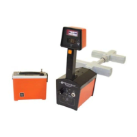
Figure 4-2: Inductive Coupling with the Metroclamp
 Loading...