25
1 Changing to a different Transmitter coupling point or coupling mode.
2 Improving the grounding connection or moving the grounding point.
3 Determine the location of the adjacent conductors. Then check to be sure that neither the direct connect cable or the ground
cable cross over any of the adjacent conductors. Re-position them if necessary.
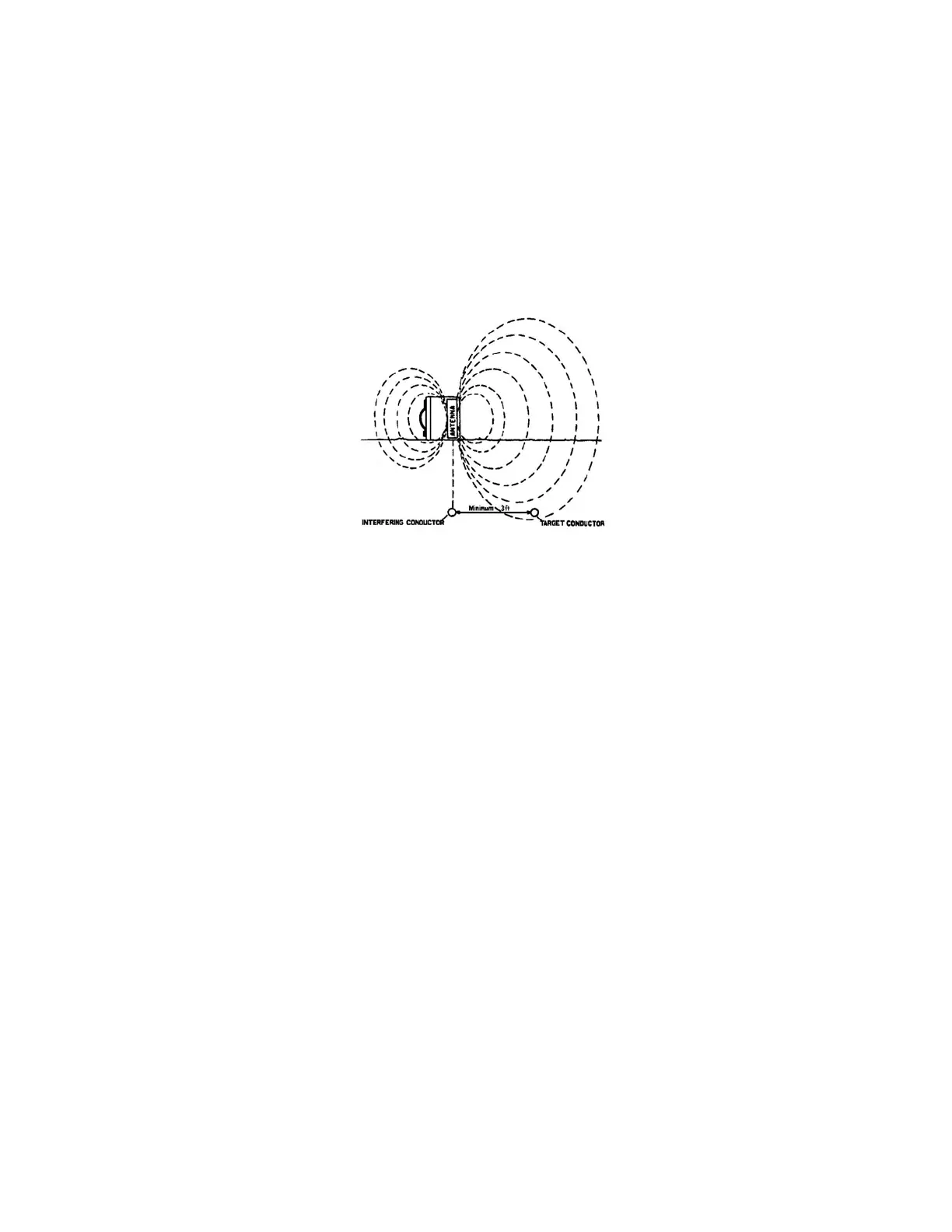
4 If you are using the Inductive (Indirect) mode, you may be able to decrease the amount of interfering signal by changing the
orientation of the Transmitter to the targeted conductor. Determine the location of the interfering conductor. Place the
transmitter, turned on its end with the bottom facing the targeted conductor, over the interfering conductor as shown in
Figure 6-2.
Figure 6-2: Position of Transmitter for Minimum Interference
6.12 Locating a Service Lateral
After you have traced the main, you may want to go back and locate the service laterals off the main. Service lateral traces are
easiest to conduct in the Inductive Mode. Two operators are required for this procedure – Operator 1 remains stationary holding
the Receiver as id to trace (Figure 4-5) over and parallel to the main. Operator 2, carrying the Transmitter (with the power on) and
maintaining a minimum of 100 ft. between himself and the Receiver, walks parallel, but 5 feet from the main on the side, he
expects to find the service laterals as shown in Figure 6-5. The field strength reading on the Receiver will increase as Operator 2
crosses over the service lateral with the Transmitter. Each time the field strength reading increases, Operator 1 signals Operator 2
and he/she marks the lateral location on the ground.
6.13 Valves, Manhole Covers, Tees and Risers
If the meter reading suddenly increases and then falls back while tracing a pipe, you have probably passed over a buried valve,
manhole cover, tee, or riser.

 Loading...