9
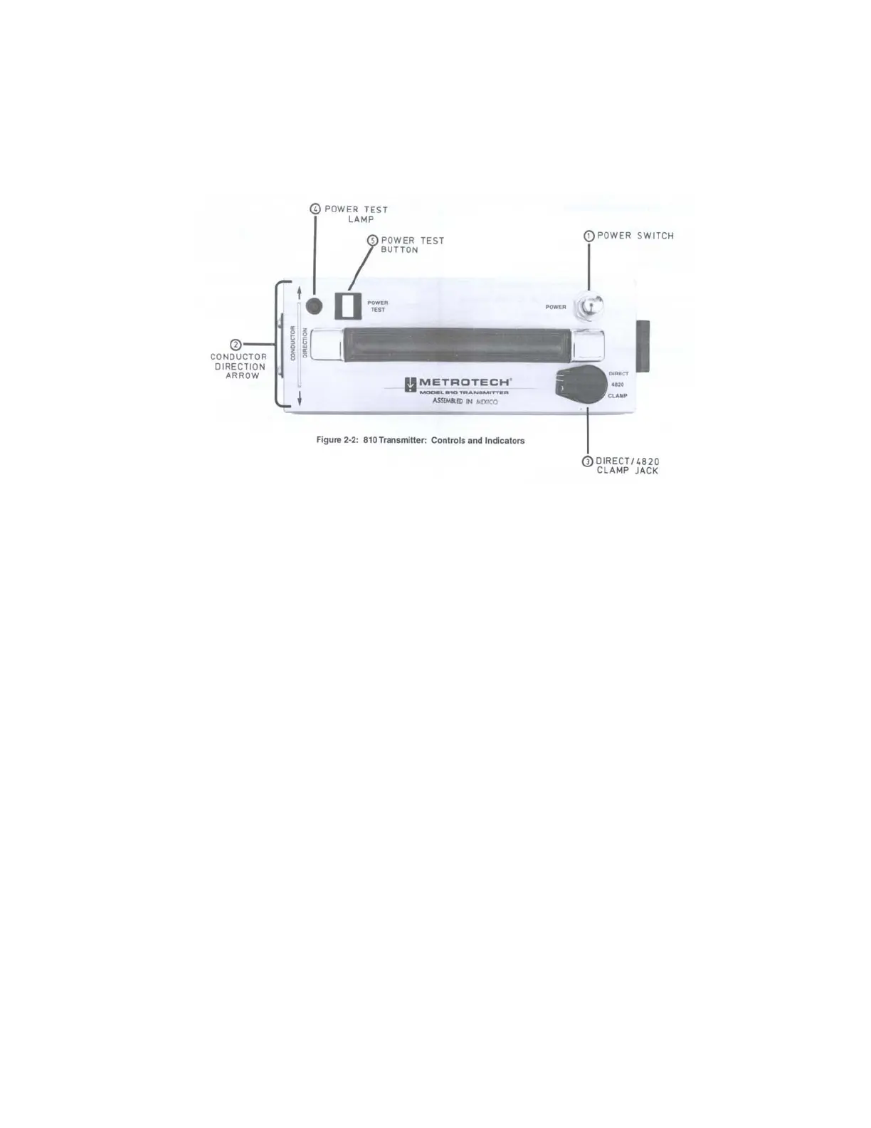
Figure 2-2: 810 Transmitter: Controls and Indicators
2.4 810 Transmitter: Controls and Indicators
Figure 2-2 Designation
1 POWER ON/OFF SWITCH
Pull this switch to turn the Transmitter on.
2 DIRECT/4820 CLAMP Output Jack
Connection point for the Direct Connect cable
Or any Metroclamp
3 CONDUCTOR DIRECTION Arrow
Orients the Transmitter when used in Inductive
Mode.
4 POWER TEST Lamp
If there is adequate battery power for operation,
this lamp will light up when you push the POWER
TEST button
5 POWER TEST Button
Push this button to determine if there is adequate battery
available for operation.

 Loading...