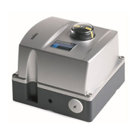
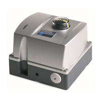
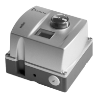
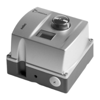
Do you have a question about the Metso ND9300H and is the answer not in the manual?
Overview of ND9000 capabilities and benefits, including performance, diagnostics, and ease of use.
Covers simplified setup and integration processes for linear and rotary valves using LUI or FieldCare.
Highlights the controller's durability and performance in demanding environmental conditions.
Features supporting proactive maintenance and diagnostics, including data access and condition monitoring.
Detailed performance and operational specifications for the ND9300H, including environmental and electrical data.
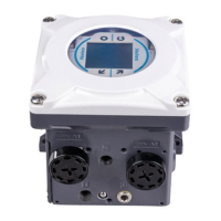
Detailed explanation of the ND9300H's architecture, features, loop-powered operation, and LUI.
Critical safety warnings and precautions for installation, operation, and maintenance to prevent injury or damage.
Steps for mounting the controller on Metso actuators with VDI/VDE mounting face, including coupling.
Step-by-step guide for initial controller configuration, including parameter verification and calibration.
Overview and access to key configuration parameters like PERF, CUTL, DIR, VTYP, and ATYP.
Defining the valve's action (open/close) upon signal failure or critical device failure.
Recognizing and understanding the fail-safe operational mode indicated on the display.
Identifying and responding to reduced performance mode due to spool valve measurement failure.
Performing automatic valve travel calibration and tuning for optimal control performance.
Performing manual valve travel calibration by driving the valve to closed and open positions.
Descriptions of failsafe error conditions detected by the controller, such as sensor failures.
Details on specific error messages like prestage cut error, sensor failures, and calibration/tuning errors.
Troubleshooting guide for mechanical and electrical issues affecting valve position and actuator movement.
| Supply voltage | 24 VDC |
|---|---|
| Power consumption | 10 W |
| Operating temperature | -20…+70°C (-4…+158°F) |
| Communication protocols | Modbus RTU, Modbus TCP/IP |
| Mounting | DIN rail |
| Communication | Modbus RTU, Modbus TCP/IP, Ethernet/IP |

