EasyManua.ls Logo

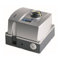
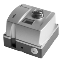
Metso ND9200F User Manual

Metso ND9200F
44 pages
To Next Page IconTo Next Page
Page #1 background imageLoading...
Page #1 background image
INTELLIGENT
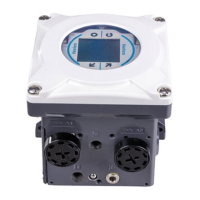
VALVE CONTROLLER
ND9200F
Rev. 2.2
Installation, Maintenance and
Operating Instructions
7 ND92F 70 en • 1/2009

Table of Contents

Questions and Answers:

Metso ND9200F Specifications

General IconGeneral
BrandMetso
ModelND9200F
CategoryController
LanguageEnglish

Summary

ND9000 Product Family Summary

Key features

Highlights the primary advantages and capabilities of the ND9000 product line.

Easy installation and configuration

Details the user-friendly aspects of installing and setting up the valve controller.

Product reliability

Describes the robust design and durability of the ND9000 for demanding environments.

Predictive maintenance

Explains features for proactive maintenance and performance monitoring.

ND9200F Intelligent Valve Controller

General

Provides an overview of the ND9200F controller's purpose and application.

Technical description

Explains the internal workings, components, and operating principles of the ND9200F.

Markings

Details the identification plate markings and their meanings.

Technical specifications

Lists the detailed technical parameters, environmental influences, and certifications.

Recycling and disposal

Provides guidelines for the proper disposal and recycling of the valve controller.

Safety precautions

Outlines essential safety measures to prevent hazards during operation and maintenance.

Mounting

General

Describes general considerations and recommendations for mounting the valve controller.

Mounting on EC and EJ actuators

Details the specific steps for mounting the controller on EC and EJ actuators.

Mounting on Metso actuators with VDI/VDE mounting face

Explains the process for mounting on Metso actuators using the VDI/VDE interface.

Mounting on linear actuator of nelesCV Globe

Provides instructions for mounting the controller on nelesCV Globe linear actuators.

Mounting on linear actuator with IEC 60534 mounting face

Details the procedure for mounting on linear actuators with IEC 60534 face.

Piping

Covers the recommended air supply and actuator connection piping.

Electrical connections

Explains how to connect the fieldbus cable and other electrical wiring.

Local User Interface (LUI)

Measurement monitoring

Describes how to view process measurements and device status via the LUI.

Guided start-up

Outlines the initial configuration steps to get the controller operational.

Configuration menu

Explains navigation and access to configuration settings through the LUI.

Mode menu

Details how to select and change operating modes via the LUI.

Configuration parameters

Covers the various parameters available for configuring the controller's behavior.

Valve travel calibration

Explains the procedures for calibrating the valve's travel range.

Special displays

Describes special display modes like UI locked, alarms, and fail-safe status.

Maintenance

Prestage

Details the removal and installation procedures for the prestage module.

Spool valve

Covers the procedures for removing and installing the spool valve.

Flame arrestor assembly

Provides instructions for handling the flame arrestor assembly.

Diaphragms

Describes the replacement process for diaphragms.

Communication circuit board

Details the removal and installation of the communication board.

Error Messages

Failsafe errors

Lists and describes errors that trigger the fail-safe mode.

Alarms

Details various alarm conditions and their corresponding messages.

Errors

Lists and explains various error messages and potential causes.

Warnings

Details warning messages indicating deviations or potential issues.

Notifications

Lists status messages indicating successful operations or cancellations.

Trouble Shooting

Mechanical/electrical defects

Provides common troubleshooting steps for mechanical and electrical issues.

Limit Switches

Introduction

Introduces the concept and general description of limit switches for the ND9200F.

Installing ND92_F/K_, ND92_F/I_ or ND92_F/B_ on a valve controller

Guides the installation of limit switch modules onto an existing valve controller.

Electrical connections

Explains the electrical wiring for limit switches, referring to diagrams.

Adjustment

Details how to adjust the cam discs for setting the limit switch points.

Removal of the limit switches

Provides instructions for removing limit switch housings and components.

Circuit diagrams

Shows the internal circuitry and connection diagrams for limit switches.

Maintenance

States that regular maintenance of limit switches is not necessary.

Tools

Ordering Spare Parts

Drawings and Parts Lists

Exploded view and parts list, ND9200F

Presents an exploded view and list of parts for the ND9200F controller.

Exploded view and parts list, ND92_F/K_, ND92_F/I__, ND92_F/B_

Shows exploded views and parts lists for limit switch variants.

Mounting parts for EC05-14 actuators, rising signal opens valve

Lists mounting parts for EC05-14 actuators with specific signal configuration.

Mounting parts for B1C/B1J 6-20 actuators

Details mounting parts required for B1C/B1J 6-20 actuators.

Mounting parts for B1C/B1J 25-50, B1C 502 and B1J322 actuators

Lists mounting parts for various B1C/B1J actuator models.

Mounting parts for Quadra-Powr® actuators

Provides mounting parts information for Quadra-Powr® actuators.

Mounting parts for linear actuators of nelesCV Globe

Details mounting parts for nelesCV Globe linear actuators.

Mounting parts for linear actuators

Lists mounting parts and instructions for linear actuators.

Connection diagrams

Illustrates the electrical connection diagrams for limit switches.

Dimensions

EC Declaration of Conformity

Type Coding