16 7 ND92F 70 en
5.5.6 Valve rotation direction, ROT
The application-specific parameter ROT defines the rela-
tionship between position sensor rotation and valve
action.
❑ Once ROT is displayed press the ? key to enter
the edit state and ROT starts to blink.
❑ Now you may select between two values by
pressing the + or - key. The value cC indicates
clockwise rotation for closing the valve and ccC
means counterclockwise to close.
❑ After the desired value is displayed, press the
key ? to conclude the operation.
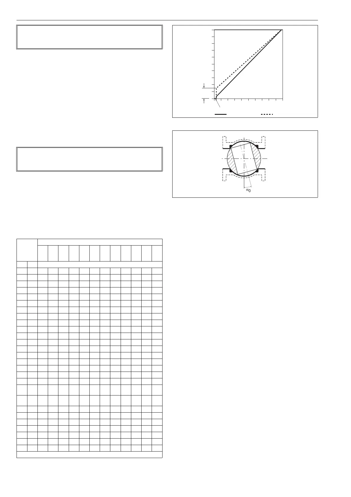
5.5.7 Valve dead angle, A0
The α
0
setting is made for Metso segment and ball valves.
This setting takes into account the "dead angle" α
0
of the
ball valves. The entire signal range is then used for effec-
tive valve opening 90° - α
0
. Use 0 % as the "dead angle"
for the valves not mentioned in Table 5.
❑ After selecting A0 on the display, press the ?
key to enter the edit state and A0 starts to blink.
The value currently selected appears as a per-
centage (%) on the display.
❑ Modify the parameter value by pressing + or -
keys alternately until the desired value appears
on the display.
❑ Press the ? key to make your selection and
return to the setting state.
5.5.8 Language selection, LANG
❑ Select between three languages EnG, GEr or FrE
using the + and - keys.
❑ To conclude press the ? key when the desired
value is shown on the display.
5.5.9 Low cut-off, low limit, high cut-off,
high limit
ND9200F supports signal cut-off and limiting in both
ends of the operating range. The configuration parame-
ters are; low cut-off, low limit, high cut-off and high limit.
❑ If the input signal is smaller than low cut-off
(TRANSDUCER_BLOCK.FINAL_VALUE_CUTOFF_LO),
the valve will be fully closed.
❑ If the input signal is smaller than low limit
(TRANSDUCER_BLOCK.FINAL_VALUE_RANGE.LO),
the valve stays in the low limit.
❑ If the input signal is greater than high cut-off
(TRANSDUCER_BLOCK.FINAL_VALUE_CUTOFF_HI),
the valve will be fully opened.
❑ If the input signal is greater than high limit
(TRANSDUCER_BLOCK.FINAL_VALUE_RANGE.HIGH),
the valve stays in the high limit.
The cut-off overrides the limit as follows:
NOTE:
Perform valve calibration and tuning always when con-
troller fail action parameter has been changed.
NOTE:
Perform valve calibration and tuning always when ROT
has been changed.
Taulukko 5 Dead angle in percentage
Valve
size
Valve series
MBV
QMBV
1)
MBV
QMBV
2)
D,
P,
C
T5,
QT5
QX-
T5
T25,
QT25
QX-
T25
R,
QR
ER-
SOFT
3)
FL
4)
ZX
mm in Dead angle, %
15 1/2 15
20 3/4 15
25 1 14 - - 25.5 19.5 - - 15 25.5 27 12.5
25/1 1/1 14.5 11
25/2 1/2 8 11
25/3 1/3 8 10
25/4 8
40 1 1/2 12 - - 24.5 12.5 - - 12 16 21 12.5
50 2 10 9 13.5 24.5 12.5 18 8 17 20.5 23 12.5
65 2 1/2 9 - - - - - - 13 - 18
8031081218816.58.598.515.5
100 4 10 8 12 16.5 8.5 16 9 8 7 14.5
125 5 12 - - - - 12 6.5 8 -
150 6 10 8 11.5 16 9 13.5 8 13.5 13
200 8 9 7 8.5 12 6.5 9.5 7 11.5
250 10 9 7 7.5 13.5 9.5 7 10.5
300 12 8 6 6.5 9.5 7.5 6 9.5
350 14 6 6 - 5 9.5
400 16 5 5.5 9.5
(14")
59.5
450 18 6 7.5
(16")
500 20 6 4.5
600 24 5.5 6
650 26 7
700 28 7 6
750 30 6
800 32 -
900 36 5.5
1) Seat supported 2) Trunnion 3) Soft seated R-valve 4) Low Cv Finetrol
Fig. 14 Principle of setting
Fig. 15 Dead angle
100
80
60
40
20
0
0 20 40 60 80 100
α
0
Position
Input signal
low cut-off safety range 2 ± 0.5 %
Basic setting α
0
setting