18 7 ND92F 70 en
The valve can now be unlocked.
5.6.5 LS status
LS shows the status of limit switches:
--- No LS active
CLO LS "Closed" active
OPE LS "Open" active
LSE LS Error, both switches activated
at the same time
5.7 Special displays
5.7.1 User interface locked
In order to prevent unauthorised access, the Local User
Interface may be locked. In this mode measurements
may be viewed but configurations and calibrations are
prohibited. You may lock and unlock the device only via
dip switch, see Fig.21. When the Local User Interface is
locked the lock symbol will be activated on the display.
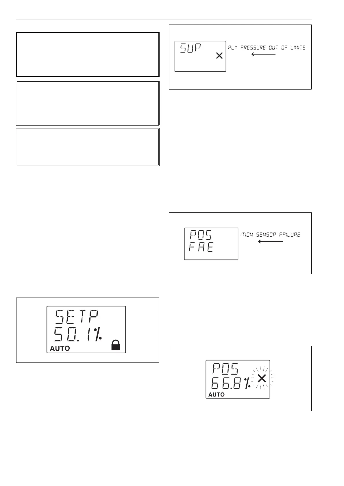
5.7.2 Online-alarm active
If an online alarm has been detected the solid & symbol
is activated. This symbol will disappear after the recov-
ery from online alarm. You may view the reason for the
alarm by viewing the latest event while pushing the =
and - keys simultaneously or by using FieldCare soft-
ware where all events may be viewed.
5.7.3 Viewing of latest event
You may view the latest event by pressing the = and -
keys simultaneously in the measurement monitoring
view. The message is scrolled on the top row of the dis-
play twice. You may stop the scrolling by pressing the ?
key. By pressing the = key, the message will disappear.
For the list of events see Chapter 7.
5.7.4 Fail-safe active
When the ND9200F detects serious device failure (set-
point, valve position and control signals) it enters fail-
safe mode, which drives the control valve into the posi-
tion defined in the parameter controller fail action (PFA).
Fail-safe mode is indicated by the display as seen in
Fig. 19. The error message is displayed until the cause
of error is eliminated and the ND9200F unit is restarted,
i.e. the power loop is momentarily disconnected.
5.7.5 Reduced Performance
When the ND9200F detects spool valve measurement
failure, it enters reduced performance mode. This is
indicated by the blinking & in the display, see Fig. 20.
In reduced performance mode valve control can not be
optimized. To correct the problem replace the spool
valve assembly and perform auto calibration.
WARNING:
Supply pressure can be connected to the valve
controller only after 1-point calibration is success-
fully completed. If supply pressure is connected to
the valve controller before successful 1-point cali-
bration, the valve may move and cause danger.
NOTE:
If an incorrect valve operation angle is given to the
valve controller during 1-point calibration, valve oper-
ation will be incorrect. In this case, you must perform
1-point calibration again with correct valve operation
angle value.
NOTE:
If the valve position is not stable (due to heavy vibra-
tion etc) during 1-point calibration, the calibration will
not end successfully. Check that the valve position is
fully stable during this operation.
Fig. 17 LUI locked
Fig. 18 Online alarm message
Fig. 19 Failsafe display
Fig. 20 Reduced performance display
scrolling text
scrolling text