EasyManua.ls Logo

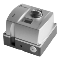
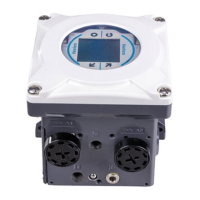
Metso neles ND9000F User Manual

Metso neles ND9000F
68 pages
To Next Page IconTo Next Page
Page #1 background imageLoading...
Page #1 background image
INTELLIGENT
VALVE CONTROLLER
ND7000H
ND9000H, ND9000F, ND9000P
Rev. 4.0
Installation, Maintenance and
Operating Instructions
7 ND90 71 en • 5/2019

Table of Contents

Other manuals for Metso neles ND9000F

Questions and Answers:

Metso neles ND9000F Specifications

General IconGeneral
Power Supply24 V DC
Enclosure RatingIP66, NEMA 4X
DisplayLCD
TypeValve controller
Communication ProtocolsHART, Foundation Fieldbus
Operating/Ambient Temperature Range-40 to +70 °C
Input Signal4-20 mA
Output Signal4-20 mA

Summary

1 PRODUCT FAMILY SUMMARY

1.1 ND9000 Overview

Details the ND9000 controller's key features, options, cost, installation, reliability, and maintenance.

2 INTELLIGENT VALVE CONTROLLERS: ND9000 & ND7000

2.2 Technical Description

Details the technical aspects of ND9000 and ND7000 controllers, including their architecture and operation.

2.4 Technical Specifications

Lists comprehensive technical specifications for ND9000 and ND7000 controllers, including environmental and electrical data.

2.6 Safety precautions

Outlines essential safety measures for handling and operating the valve controllers to prevent injury or damage.

4 MOUNTING

4.2 Mounting Parts for Metso Actuators

Details the mounting procedure for ND9100, ND9400, ND7100 on Metso actuators with VDI/VDE face.

4.3 Mounting on Neles VC/VD and Linear Actuators

Describes mounting ND9100, ND7100 and ND9200, ND7200, ND9300 on Neles actuators with IEC 60534 face.

4.5 Electrical connections

Details electrical connections for ND9000H/ND7000H and ND9000F/ND9000P models.

4.5.3 Control wiring, ND9000H and ND7000H, Ex i

Illustrates control wiring diagrams for ND9000H and ND7000H in Ex i hazardous locations.

4.5.4 Control wiring, ND9000F/P, Ex 'ia' for Zone 0 / Division 1

Illustrates control wiring diagrams for ND9000F/P in Ex 'ia' hazardous locations.

4.5.5 Control wiring, ND9000F/P, Ex 'ic' for Zone 2 / Division 2

Illustrates control wiring diagrams for ND9000F/P in Ex 'ic' hazardous locations.

4.5.6 Control wiring, ND9000 and ND7000, Ex d

Illustrates control wiring for ND9000/7000 in Ex d hazardous locations.

4.5.7 Control wiring, ND9000F and ND9000P, Ex d

Illustrates control wiring for ND9000F/P in Ex d hazardous locations.

5 LOCAL USER INTERFACE (LUI)

5.2 Guided start-up

Guides users through initial setup and configuration of valve parameters using the LUI.

5.5 Configuration parameters

Details various configuration parameters accessible via the LUI, including performance and signal settings.

5.5.1 Performance level, PERF

Explains how to adjust the performance level (PERF) for optimal valve control.

5.6 Valve travel calibration

Explains the process of calibrating valve travel to optimize internal control parameters.

5.6.1 AUTO calibration function

Details the automatic calibration process for valve travel and its progress.

6 MAINTENANCE

6.2 Spool Valve Operations

Covers removal and installation procedures for the spool valve assembly.

7 ERROR MESSAGES

7.1 Failsafe errors

Lists and explains failsafe errors detected by the controller.

7.2 Alarms

Lists and explains alarm conditions detected by the controller.

7.3 Errors

Lists and explains general errors detected by the controller, such as sensor failures.

7.4 Warnings

Lists and explains warning messages related to operation, limits, and performance.

8 TROUBLE SHOOTING

8.1 Mechanical/electrical defects

Provides troubleshooting steps for common mechanical and electrical issues with the valve controller.

9 ND9000 WITH LIMIT SWITCHES

16 TYPE CODING

16.1 Intelligent Valve Controller Type Coding

Explains the type coding system for ND9000 and ND7000 intelligent valve controllers.

Related product manuals