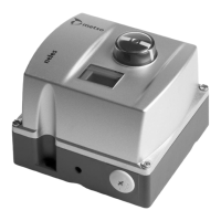
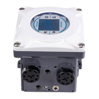
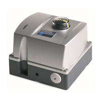
Do you have a question about the Metso Neles ND9100P and is the answer not in the manual?
Lists main capabilities and diagnostic features of the ND9000 product family.
Details available communication options, limit switches, and special finishes.
Highlights benefits like low energy consumption and future-proofing.
Explains how the device improves control performance and accuracy.
Describes the ease of setup for various actuators and valves.
Emphasizes interoperability with other manufacturers' hardware and software.
Details compatibility and features for fieldbus communication.
Covers design for harsh environments and durable components.
Outlines features for proactive maintenance and diagnostics.
Provides an overview of the manual's scope and intended use for the ND9100P.
Explains the microcontroller's role and key measurements.
Details the information found on the valve controller's identification plate.
Lists detailed parameters for general, environmental, enclosure, pneumatics, and electronics.
Provides guidelines for environmentally responsible end-of-life handling.
Outlines critical safety warnings and cautions for operation and maintenance.
Step-by-step guide for attaching the controller to EC and EJ actuators.
Instructions for mounting on Metso actuators with a specific interface.
Details the process for mounting on nelesCV Globe linear actuators.
Instructions for installing on linear actuators using IEC 60534 standard.
Covers air supply connection and recommendations for piping.
Explains Profibus PA power and communication wiring.
Describes how to view valve position, setpoint, and other parameters.
Guides the user through initial setup of critical parameters.
Explains navigation through the menu structure for settings.
Details how to select between AUTO and MAN operating modes.
Allows adjustment of valve position control tuning for different responses.
Sets the safety range for valve closing against mechanical stops.
Compensates for non-linearity in linear valve linkages.
Informs the device about the actuator type for optimal control.
Defines valve behavior during signal failure or device malfunction.
Defines the relationship between sensor rotation and valve action.
Accounts for the 'dead angle' in Metso segment and ball valves.
Configures the device's address on the Profibus network.
Allows choosing the display language from English, German, or French.
Configures signal limits for valve full open/close or partial positioning.
Details the automatic process of driving the valve through its full travel.
Describes manual calibration by driving the valve using controls.
Optimizes internal control parameters for valve position control.
Provides a method for calibration when normal methods are not feasible.
Displays the status of limit switches (active, error, etc.).
Explains how to lock/unlock the LUI to prevent unauthorized access.
Indicates when an alarm condition is detected and how to view it.
Describes how to access and view the most recent system events.
Shows how the device indicates a fail-safe mode due to serious failure.
Indicates when performance is reduced due to spool valve issues.
Explains how to enable/disable write protection for parameters.
Covers handling, removal, and installation of the prestage unit.
Step-by-step instructions for removing the prestage module.
Instructions for installing a new prestage module.
Details maintenance procedures for the spool valve assembly.
Steps for removing the spool valve assembly for cleaning or replacement.
Procedures for installing the spool valve assembly correctly.
Covers maintenance of the communication circuit board.
Instructions for removing the communication circuit board.
Steps for installing a new communication circuit board.
Lists error messages indicating critical device failure requiring immediate attention.
Details various alarm conditions like deviation, stiction, and load issues.
Lists specific error codes, their descriptions, and recommended actions.
Explains warning messages related to operational limits and component usage.
Lists messages indicating successful operations or specific states.
Lists common issues and potential causes related to hardware.
Introduces the ND9100P/B06 variant with limit switches for valve indication.
Explains the function and availability of limit switches on the ND9100P/B06.
Describes the identification plate markings for the limit switch version.
Lists detailed specifications for the ND9100P/B06, including microswitch details.
Provides installation steps for the limit switch variant.
Details electrical connection requirements for the limit switch setup.
Guides on adjusting the limit switch switching points using cam discs.
Instructions for removing the limit switch components.
Shows circuit diagrams for the limit switch functionality.
States that regular maintenance of the limit switch is not necessary.
Lists any special tools required for maintenance or installation.
Provides information needed when ordering spare parts.
Visual breakdown and list of components for the standard ND9100P.
Visual breakdown and list of components for the ND9100P/B06 variant.
Lists parts required for mounting on specific EC/EJ actuator models.
Lists parts needed for mounting on B1C/B1J6-20 actuator types.
Lists mounting parts for specific B1C/B1J actuator models.
Details mounting parts required for Quadra-Powr® actuators.
Lists components for mounting on nelesCV Globe linear actuators.
Lists parts for mounting on various linear actuators.
Provides wiring diagrams for the ND9100P/B06 with limit switches.
Illustrates the control wiring concept and FISCO rules for hazardous locations.
Shows dimensional drawings and specifications for ND9100 and ND9100/B.
| Brand | Metso |
|---|---|
| Model | Neles ND9100P |
| Category | Controller |
| Language | English |


