7 ND92F 70 en 19
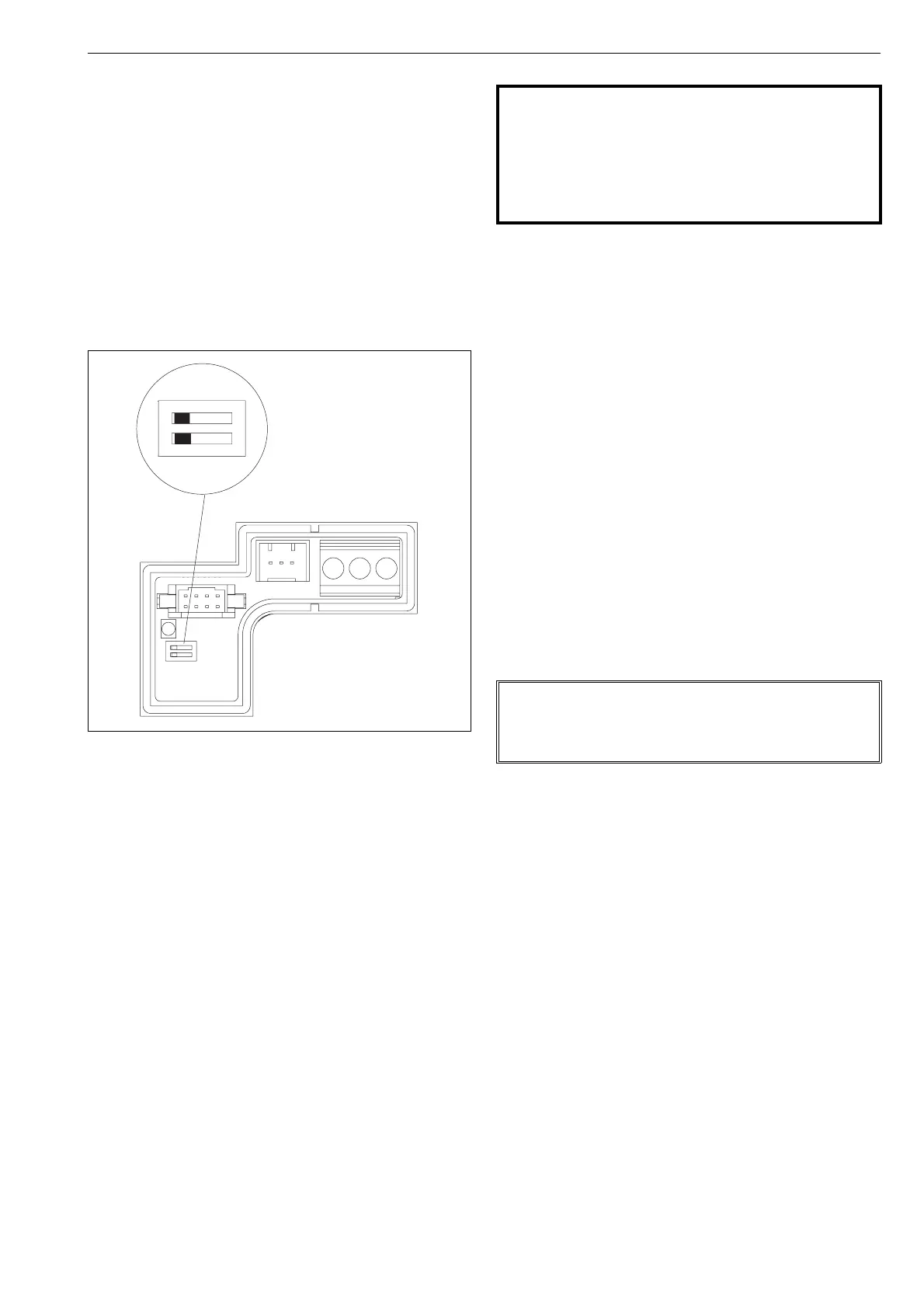
5.8 Write protection
The ND9200F is delivered from the factory with HW
write protection OFF as the default setting. Reading
and changing parameters is thus allowed. Write protec-
tion can be enabled with the switch (DIP1) located on
the circuit board (Fig. 21).
Write protection protects all write access to all writeable
parameters of the device. Changing the parameters
from the LUI or Fieldbus configurator is thus not
allowed.
The simulation switch is OFF as the default setting. A0
block simulation is thus disabled. The simulation can be
enabled with the switch (DIP2) located on the circuit
board (Fig 21).
6 MAINTENANCE
The maintenance requirements of the ND9200F valve
controller depend on the service conditions, for
instance, the quality of instrument air. Under normal
service conditions there is no requirement for regular
maintenance.
When maintaining the ND9200F ensure that the supply
air is shut off and pressure is released. In the following
text the numbers in brackets ( ) correspond to the part
numbers in the exploded view as shown in Chapter 11,
unless otherwise stated.
The ND9200F valve controller includes the following
interchangeable modules: prestage unit (120), spool
valve (193), communication circuit board with optional
position transmitter (215).
The spool valve is located on the bottom side of the
device while the other modules are located below the
covers (100) and (39). In the event of failure the whole
module must be changed. The module retrofit must be
assembled in a clean, dry environment. In reassembly
apply a thread-locking compound (for instance, Loctite
243) and tighten the screws firmly.
6.1 Prestage
6.1.1 Removal
❑ Loosen the M8 stop screw (110) in the position
indicator (109) and turn the position indicator
from the shaft (11). Remove the inner cover (39)
attached with M3 screws (42, 3 pcs).
❑ Unplug the prestage wire connector from the
spool sensor board (180). Unscrew the M4
screws (139, 2 pcs.) and lift up the prestage
module. Remove the O-ring (140).
6.1.2 Installation
❑ Place a new O-ring (140) into the groove in the
housing and press the prestage into place. Make
sure the nozzle is guided into the O-ring properly.
The screws guide the prestage body into the cor-
rect position. Tighten the screws (139) evenly.
❑ Push the prestage 2-pole wire connector into the
socket on the spool sensor board. The wire con-
nector can only be fitted in the correct position.
Replace the inner cover (39) and tighten the M3
screws.
Fig. 21 Write protection
12
ON
Ex d WARNING:
Service of the cylindrical flameproof joints is not
allowed.
This includes the diaphragm cover (part 171), flame
arrester plunger (part 200), their mating surfaces in
the housing (part 2) and the shaft assembly fixed in
the housing.
NOTE:
The prestage must be handled carefully. In particular
the moving parts of the prestage should not be
touched when the inner cover (39) is not in place.