4 7 ND92F 70 en
2 ND9200F INTELLIGENT VALVE
CONTROLLER WITH FOUNDATION
FIELDBUS COMMUNICATION
2.1 General
This manual incorporates Installation, Maintenance and
Operation Instructions for the Metso ND9200F intelligent
valve controller. The ND9200F may be used with either
cylinder or diaphragm type pneumatic actuators for
rotary or linear valves.
2.2 Technical description
The ND9200F is a fieldbus powered microcontroller-
based intelligent valve controller. The ND9200F configu-
ration can be done either using local push buttons or
FOUNDATION Fieldbus configurator.
The powerful 32-bit microcontroller controls the valve
position. The measurements include:
❑ Input signal
❑ Valve position with contactless sensor
❑ Actuator pressures, 2 independent measurements
❑ Supply pressure
❑ Spool valve position
❑ Device temperature
Advanced self-diagnostics guarantees that all measure-
ments operate correctly. Failure of one measurement
does not cause the valve to fail if the input signal and
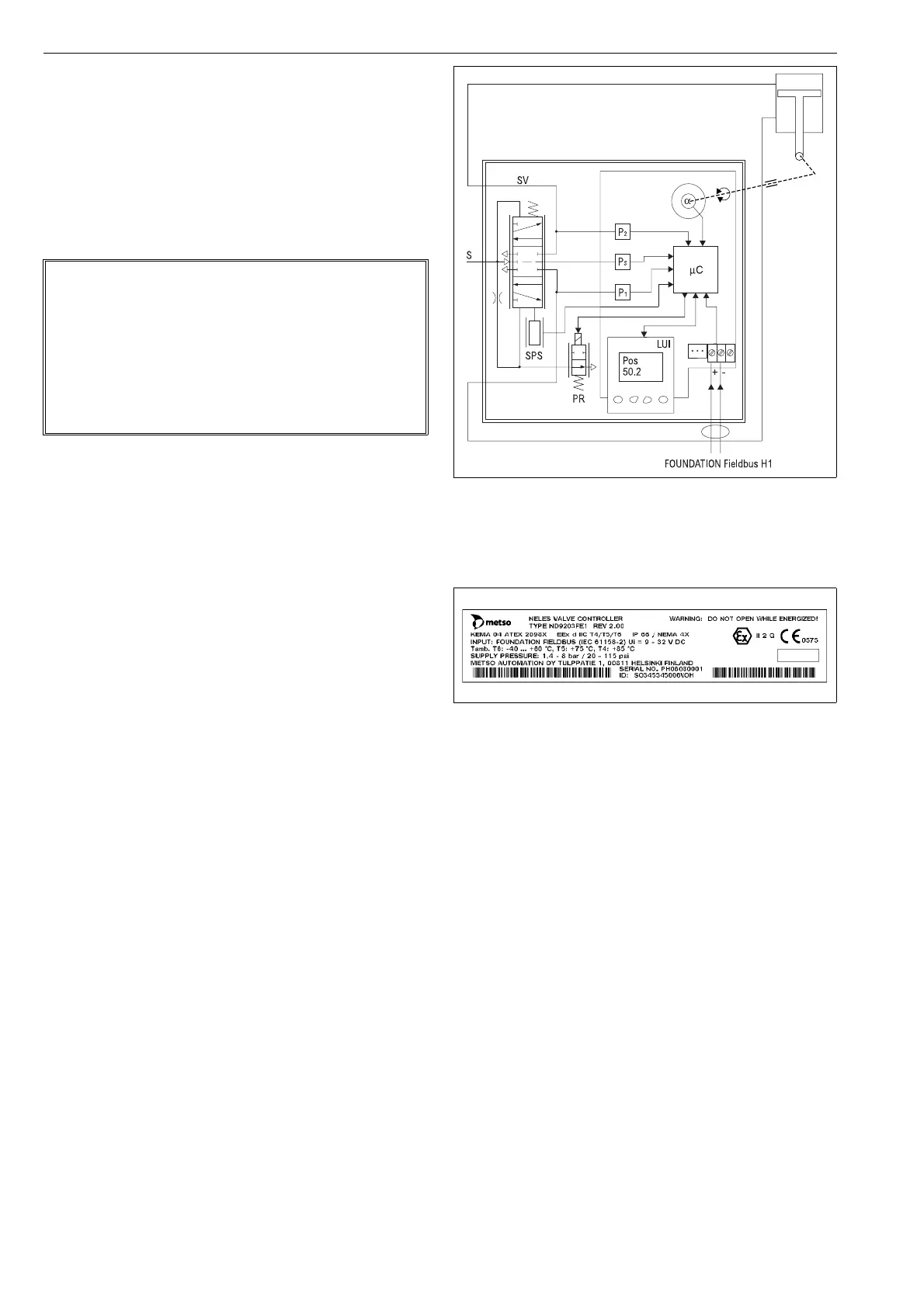
position measurements are operating correctly. After
connections of electric signal and pneumatic supply the
micro controller (µC) reads the input signal, position sen-
sor (α), pressure sensors (Ps, P1, P2) and spool position
sensor (SPS). A difference between input signal and
position sensor (α) measurement is detected by the con-
trol algorithm inside the µC. The µC calculates a new
value for prestage (PR) coil current based on the infor-
mation from the input signal and from the sensors.
Changed current to the PR changes the pilot pressure to
the spool valve. Reduced pilot pressure moves the spool
and the actuator pressures change accordingly. The
spool opens the flow to the driving side of the double
diaphragm actuator and opens the flow out from the
other side of the actuator. The increasing pressure will
move the diaphragm piston. The actuator and feedback
shaft rotate clockwise. The position sensor (α) measures
the rotation for the µC. The µC using control algorithm
modulates the PR-current from the steady state value
until a new position of the actuator according to the input
signal is reached.
2.3 Markings
The valve controller is equipped with an identification
plate sticker (Fig. 2).
Identification plate markings from top to bottom include:
❑ Type designation of the valve controller
❑ Revision number
❑ Enclosure class
❑ Input signal (voltage range)
❑ Input resistance
❑ Maximum supply voltage
❑ Operational temperature
❑ Supply pressure range
❑ Contact details of the manufacturer
❑ CE mark
❑ Manufacturing serial number TTYYWWNNNN*)
*) Manufacturing serial number explained:
TT= device and factory sign
YY= year of manufacturing
WW = week of manufacturing
NNNN = consecutive number
Example: PH08011234 = controller, year 2008, week 1,
consecutive number 1234.
NOTE:
The selection and use of the valve controller in a specific
application requires close consideration of detailed
aspects. Due to the nature of the product, this manual
cannot cover all the likely situations that may occur when
installing, using or servicing the valve controller.
If you are uncertain about the use of the controller or its
suitability for your intended use, please contact Metso’s
Automation business for more information.
Fig. 1 The principle of operation
Fig. 2 Identification plate