9
3.7 Installation types
Theoverviewtableshowsallpermissibleinstallationtypes
includingtheassociatedtestloadsaccordingtoIEC61215.
Thefollowingtablesshowindetailthedierentassembly
variants(sketches),thepermissibleassociatedxingareas
andthecorrespondingmaximumpressureandsuctionloads.
Suitablefasteningvariantscanbedevelopedinconsultation
withMBIforassemblywithunspeciedinstallationtypesor
withincreasedloads.
Legend:
CP: Clamppoint
CL: Clampline
MP: Mountingpointonframe
IP: Installationprole/Insertionprole
…1: Installationonlongmoduleside
…2: Installationonshortmoduleside
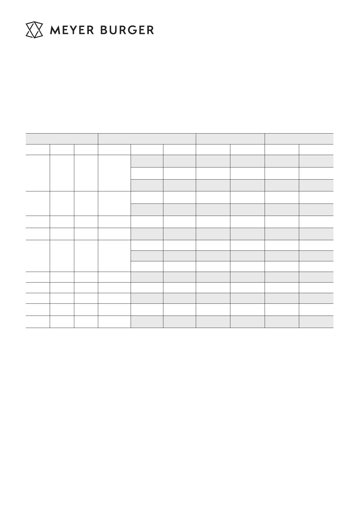
Module Installation type Design load Test load (1.5x safety)
WHITE BLACK GLASS Name L [mm] W [mm] Pressure [Pa] Suction [Pa] Pressure [Pa] Suction [Pa]
x x x CP1
320 4000 2666 6000 4000
200-450 3600 1600 5400 2400
0-550 1600 1600 2400 2400
x x x CP1a
200-450 3200 1600 4800 2400
0-550 1600 1600 2400 2400
x x x
CP2
160-210 1600 1600 2400 2400
x x x CP2a 0-300 1600 1600 2400 2400
x x x CL1
320 3600 2666 5400 4000
200-450 3600 1600 5400 2400
0-550 1600 1600 2400 2400
x x x CL2 0-300 1600 1600 2400 2400
x x x IP1 3600 2666 5400 4000
x x x IP2 1600 1600 2400 2400
x x
MP1
320 4000 2666 6000 4000
x x
MP1a
320 3600 1600 5400 2400