13
Adjusting MTG-3D Top Grid Uptilt
With the MTG-3D Top Grid’s rear link in the extended
position (as shown in Figure 17 and Figure 18), the front
CamLink can be adjusted to provide between 1˚ and
5˚ of uptilt. The MTG-3D Top Grid’s rear link works in
combination with its front CamLink to produce the desired
angle of uptilt.
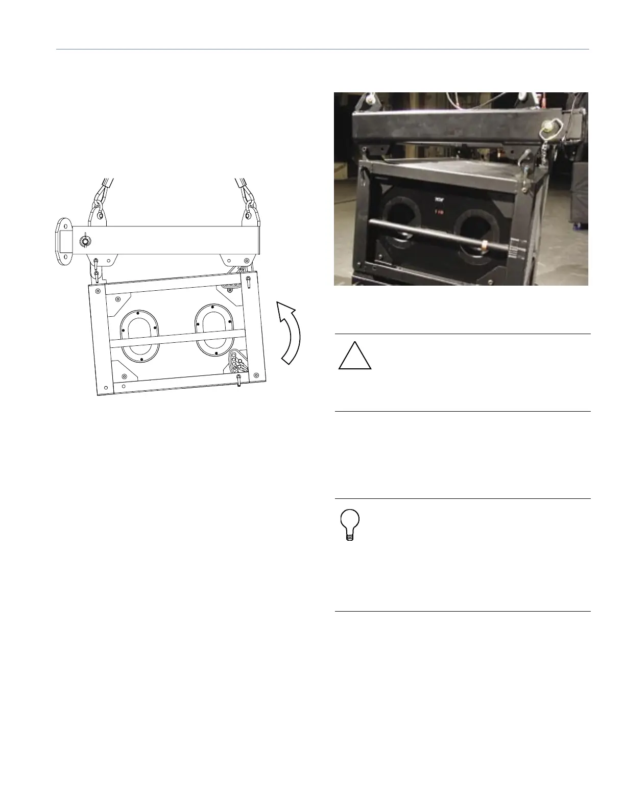
Figure 17. The MTG-3D Top Grid’s link in the extended
position
Figure 18 shows the MTG-3D Top Grid with the rear link
extended. Note the direction of tilt with this conguration.
Figure 18. MTG-3D with the rear link extended
CAUTION: The MTG-3D Top Grid’s rear link
must ALWAYS be installed when hanging an
M3D system. NEVER install a QRP into the
MTG-3D Top Grid without using the MTG-3D
Top Grid’s 5˚ rear link.
1. Once the loudspeaker’s rear links are pinned into
the retracted or extended position as required of the
MTG-3D Top Grid’s rear link, unpin the CamLinks from
the MTG-3D MTG-3D Top Grid as shown in Figure 19.
TIP: You can mount laser devices, such as
item 4 in Figure 5, on top of the array to
determine the top cabinet orientation with
respect to actual venue seating. Additionally,
you can mount the laser on any cabinet in the
array to determine that the system is properly
aimed. These devices can be congured to
be controlled from the ground.