31
CONFIGURATION G
In conguration G, the steel cables are connected to a
single lift point from the four rigging points on the MTG-3D
Top Grid.
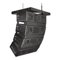
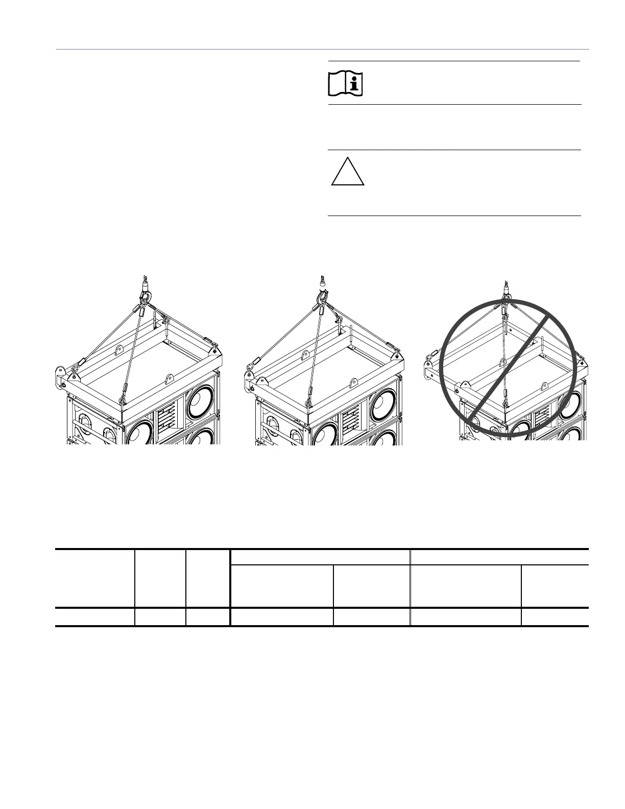
The array is lifted from a single point attached to each of the
MTG-3D Top Grid corner lifting points as shown in Figure
40. An array of up to 16 M3Ds can be supported.
The four-way bridle may be attached to each corner
of the MTG-3D Top Grid with four 5/8-inch or four 3/4-
inch shackles. The combined weight of the maximum
combination of M3Ds and M3D-Subs or other
loudspeakers, such as MSL-4s and CQs, which can be
under-hung in this conguration, cannot exceed the total
equivalent weight of the allowable number of M3Ds as
shown in Table 13.
NOTE: The lift mechanism must be rated to
support the total weight of the entire array.
The array must have suitable tie-downs to eliminate sway
and twist.
CAUTION: DO NOT use the MTG-3D Top
Grid in the extended position when an array
is hung from a single point as shown in
Figure 40.
BRP 1 BRP 2 DO NOT use this hanging
conguration (BRP 3)
Figure 40. Single point pickup conguration
Table 13. Suspended Weight and Quantity of M3D Loudspeakers
Bridle Leg
Lengths
Angle
Between
Bridle
and Grid
α (deg)
Max
Top
Grid
Angle
5:1 Safety Factor 7:1 Safety Factor
Maximum Allowable
Suspended Weight
Maximum
Allowable Qty.
of M3Ds
Maximum Allowable
Suspended Weight
Maximum
Allowable
Qty. of M3Ds
3.25 ft. (990 mm) 43˚ ±25˚
7089 lbs (3215 kg)
1 to 16
7089 lbs (3215 kg)
1 to 16