24
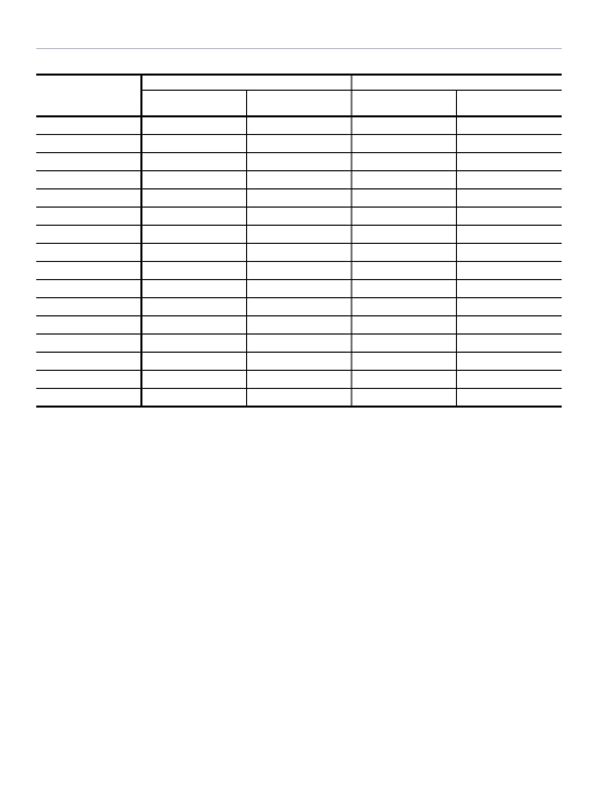
Table 6. Minimum Allowable Bridle Leg Lengths with Varying Number of M3D Loudspeakers
Qty. of M3Ds
5:1 Safety Factor 7:1 Safety Factor
Angle Between Bridle
and Grid α (deg)
Minimum Allowable
Bridle Leg Lengths
Angle Between Bridle
and Grid α (deg)
Minimum Allowable
Bridle Leg Lengths
1 51˚ 2.00 ft. (610 mm) 51˚ 2.00 ft. (610 mm)
2 51˚ 2.00 ft. (610 mm) 51˚ 2.00 ft. (610 mm)
3 51˚ 2.00 ft. (610 mm) 51˚ 2.00 ft. (610 mm)
4 51˚ 2.00 ft. (610 mm) 51˚ 2.00 ft. (610 mm)
5 51˚ 2.00 ft. (610 mm) 51˚ 2.00 ft. (610 mm)
6 51˚ 2.00 ft. (610 mm) 56˚ 2.25 ft. (690 mm)
7 51˚ 2.00 ft. (610 mm) 60˚ 2.50 ft. (760 mm)
8 56˚ 2.25 ft. (690 mm) 63˚ 2.75 ft. (840 mm)
9 60˚ 2.50 ft. (760 mm) 66˚ 3.00 ft. (910 mm)
10 60˚ 2.50 ft. (760 mm) 68˚ 3.50 ft. (1070 mm)
11 63˚ 2.75 ft. (840 mm) 71˚ 3.75 ft. (1140 mm)
12 66˚ 3.00 ft. (910 mm) 71˚ 3.75 ft. (1140 mm)
13 66˚ 3.00 ft. (910 mm) 72˚ 4.00 ft. (1220 mm)
14 67˚ 3.25 ft. (990 mm) 73˚ 4.25 ft. (1300 mm)
15 68˚ 3.50 ft. (1070 mm) 74˚ 4.75 ft. (1450 mm)
16 71˚ 3.75 ft. (1140 mm) 76˚ 5.00 ft. (1520 mm)
When calculating allowable lifting loads and bridle leg
lengths for the lifting condition illustrated in Figure 35, use
Table 5 and Table 6 to determine the maximum number of
M3Ds and allowed bridle leg lengths required to conform to
the appropriate safety factor for the venue.
The distance between lifting lugs in the conguration shown
in Figure 35 is 29.35 inches (746 mm).