Do you have a question about the Meyer Sound MTS-4 and is the answer not in the manual?
| frequency response | 30 Hz – 16 kHz |
|---|---|
| maximum peak SPL | 140 dB |
| dynamic range | > 110 dB |
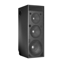
| sub frequency | 18” diameter |
|---|---|
| low frequency | 15” diameter |
| middle frequency | 12” diameter |
| type | Complementary power MOSFET output stages class AB/H |
|---|---|
| burst capability | 2480 Watts (620 Watts/channel) |
| THD, IM, TIM | < .02 % |
| type | 10 kΩ impedance, electronically balanced |
|---|---|
| connector | XLR (A-3) male and female |
| nominal input level | +4 dBu (1.23 Vrms) |
| automatic voltage selection | 85 – 134 V / 165 – 264 V; 50 Hz / 60 Hz |
|---|---|
| max continuous RMS current | 115 V: 14 A 230 V: 7 A 100 V: 16 A |
| max burst RMS current | 115 V: 26 A 230 V: 13 A 100 V: 30 A |
| dimensions | 21.25” W x 56.75” H x 30” D |
|---|---|
| weight | 280 lb (127 kg) |
| rigging working load | 600 lb |
Details on how the MTS-4 handles AC voltage, including operating ranges, auto-selection, and brown-out behavior.
Important electrical and safety precautions, including proper grounding, cord usage, and liquid avoidance.
Details on the MTS-4's balanced audio input impedance and XLR connector wiring conventions.
Explains how the TruPower limiting system works to optimize performance and protect drivers.
Recommends Meyer Sound tools for system analysis, phase alignment, and equalization.
Lists and briefly describes related Meyer speakers like CQ, PSW-4, and 650-P.
Explains combining MTS-4 and PSW-4 for enhanced low-frequency power and system phase.
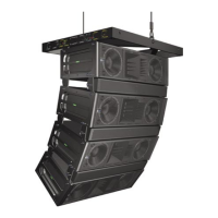
Illustrates an example system integration using LD-1A with various Meyer speakers in a large venue.
Explains how TPL LEDs can indicate driver problems like short circuits or open voice coils.
Directs users to specific procedures for inspecting and replacing high or low drivers.
Details methods for checking driver polarity to ensure proper system performance and prevent damage.
Test procedure to verify polarity between drivers within a single MTS-4 cabinet.
Test procedure to verify polarity between two adjacent MTS-4 loudspeakers.
Discusses the trade-offs in array design between on-axis power and smooth transitions.
Covers specific considerations for low-frequency array design due to varying beam widths.
Explains the impact of speaker placement and coupling with surfaces on LF response.
Details test results for coverage angles and SPL for various MTS-4 array configurations.
Warnings about disconnecting power, proper grounding, and avoiding wet locations.
Precautions against water ingress, overheating, and user serviceability of the unit.