MFJ-209 SWR Analyzer Instruction Manual
11
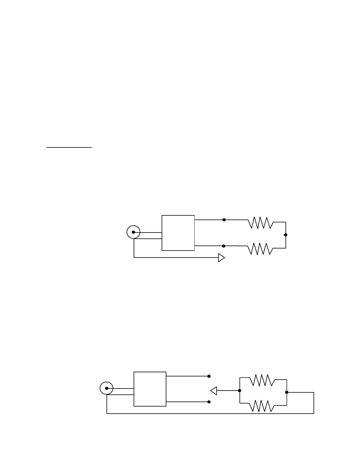
TESTING RF TRANSFORMERS
RF transformers that are designed with a 50 ohm winding can be easily and accurately tested
with the MFJ-209.
The 50 ohm winding is connected through a short 50 ohm cable to the "ANTENNA"
connector on the MFJ-209. The other winding(s) of the transformer is then terminated with a
low inductance resistor that is equal to the winding's impedance. The MFJ-209 can then be
swept through the desired transformer frequency range. The SWR and bandwidth of the RF
transformer can be measured.
Testing Baluns
Baluns can be tested by connecting the 50 ohm unbalanced side to the MFJ-209 "ANTENNA"
connector. The balun must be terminated with two equal value load resistors in series. The
resistor combination must have resistance total that is equal to the balun impedance. A pair of
100 ohm carbon resistors must be used to test the 200 ohm secondary of a 4:1 balun (50 ohm
input).
The SWR is measured by moving a jumper wire from point "A" through point "C".
A
B
C
BALUN
Clip Lead
"ANTENNA"
To the MFJ-249's
connector
A properly designed current balun, the type that is the most effective and usually handles the
most power, should show a low SWR over the entire operating range of the balun with the clip
lead in any of the three positions.
A well-designed voltage balun should show a low SWR over the entire operating range when
the clip lead is in position "B". It will show a poor SWR when the clip lead is in position "A"
and "C".
A voltage balun should also be tested by disconnecting the outer connections of the two
resistors and connecting each resistor in parallel. If the balun is operating properly the SWR
will be very low with the resistors connected from either output terminal to ground.
BALUN
"ANTENNA"
To the MFJ-249's
connector