MFJ-209 SWR Analyzer Instruction Manual
13
The MFJ-209 can be used to measure the resonant frequency of tuned circuits by two methods.
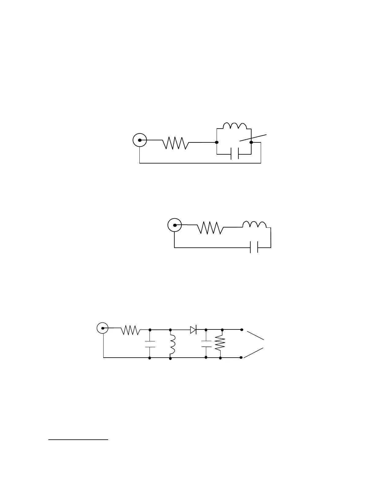
The first method involves placing a 50 ohm resistor in series with the MFJ-209 "ANTENNA"
connector. The MFJ-209 connects through the resistor to the parallel tuned circuit. This
circuit is for high capacitance values.
Tune the MFJ-209's frequency until the "SWR" meter reaches the highest SWR. This is the
resonant frequency of the load.
"ANTENNA"
To the MFJ-249's
connector
All leads should be short
50 ohms
Hi - "C"
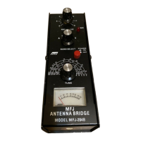
For high inductance values a series LC circuit should be used to measure resonant frequency.
The inductor and capacitor should be connected in series through a 50Ω low inductance
carbon resistor across the "ANTENNA" connector on the MFJ-209.
"ANTENNA"
To the MFJ-249's
connector
All leads should be short
50 ohms
Hi - "L"
Tune the MFJ-209's frequency until the "SWR" meter reaches the lowest SWR. This is the
resonant frequency of the load.
An external diode detector and volt meter can also be used to measure the resonant frequency
of circuits. The maximum meter reading occurs at the resonant frequency.
"ANTENNA"
To the MFJ-249's
connector
1N34
.01 10K
Measure the voltage
between these points
with a Hi-Z meter
All leads should be short
A second method of determining the resonant frequency is by using a small three or four link
coil to magnetically couple to a tuned circuit for testing. The coil should be wound around the
inductor in the tuned circuit. This magnetically couples the MFJ-209 to the resonant circuit.
The frequency of the MFJ-209 is adjusted for a dip on the "SWR" meter. The dip occurs at the
approximate resonant frequency of the tuned circuit.
Testing RF Chokes