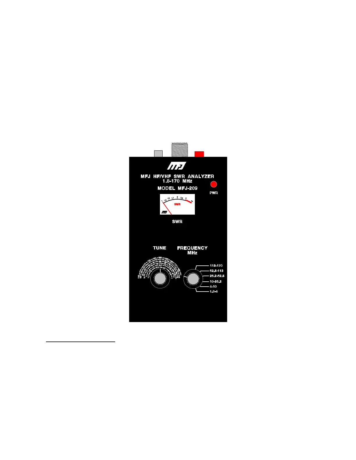
MFJ-209 SWR Analyzer Instruction Manual
4
OPERATION OF THE MFJ-209
After the MFJ-209 is connected to a proper power source the red on-off button can be
depressed to apply power. When pressed, the red button should lock into position.
The "ANTENNA" connector (SO-239 type) on the top of the MFJ-209 provides the SWR
bridge output connection. To measure SWR, this connector must be connected to the load or
device under test.
Warning: Never apply power to the "ANTENNA" connector.
SWR and the MFJ-209
Some understanding of transmission line and antenna behavior is necessary to use the MFJ-209
properly. For a thorough explanation the ARRL Handbooks or other detailed textbooks can
be used for reference.
SWR is the ratio of a load impedance to source impedance. Since nearly all feedlines and radio
equipment used in amateur service are 50 ohms, this instrument is designed to measure the
system SWR normalized to 50 ohms. For example a 150 ohm load placed across the
"ANTENNA" connector will give an SWR reading of 3:1 .