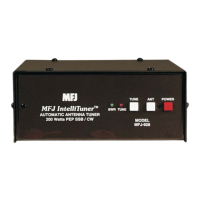
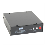
MFJ-928 Compact IntelliTuner Automatic Antenna Tuner Instruction Manual
© 2005 MFJ Enterprises, Inc.
9
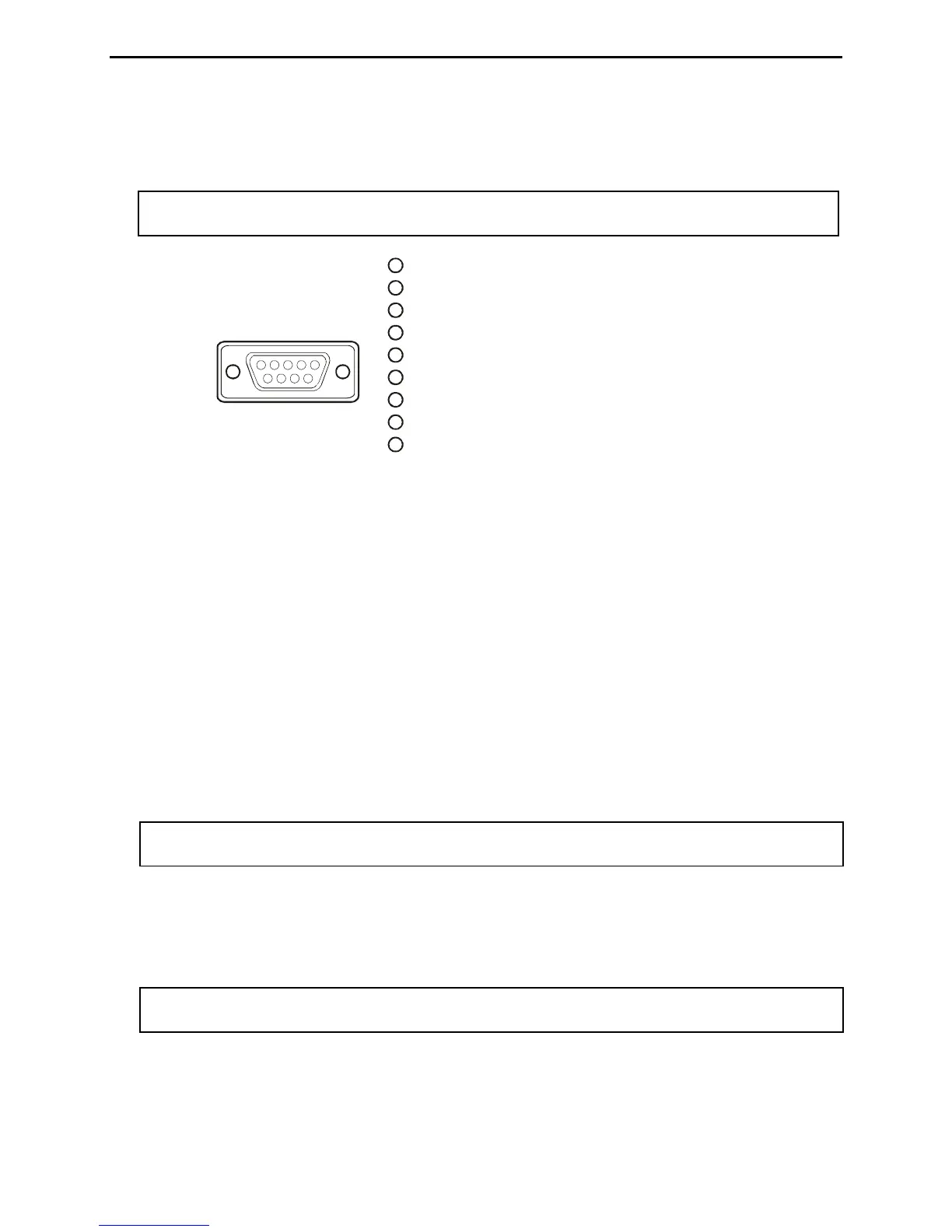
The MFJ-5114Y2 interface provides control between a Yaesu radio and the MFJ automatic tuner.
Supported Yaesu radios are FT-847 and any Yaesu radio with compatible CAT system. Push the
[TUNE] button on the tuner for 0.5 to 2 seconds to start the tuning process.
Note: The CAT port on the FT-847 does not have a +13.8 volts connection, so a separate DC
power supply must be used to power the MFJ-928.
Pin 1 is not connected.
Pin (TX) connects to pin 6 of Radio Interface Plu
Pin ( ) connects to pin 8 of Radio Interface Plug.
Pin 4 is not connected.
Pin (Ground) connects to pins 4 and of Radio Interface Plug
Pin 6 is not connected.
Pin 7 is not connected.
Pin 8 is not connected.
Pin 9 is not connected.
2g.
3RX
55 .
Yaesu
Rear Panel View
11 2345
6789
1
1
2
3
4
5
6
7
8
9
Figure 10. Yaesu Interface Cable (FT-847).
The MFJ-5124Y3 (yes, the MFJ-5124Y3) interface provides power and control between a Yaesu
radio and the MFJ automatic tuner. Supported Yaesu radios are FT-857, FT-897, and any Yaesu
radio that supports the Yaesu FC-30 tuner. Make sure to set jumper JP2 to the “I” position to use the
MFJ-5124Y3. Press and hold in the [A](TUNE) key on the radio for one second to initiate automatic
tuning.
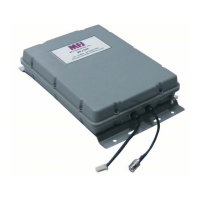
• Transmitter: SO-239 connector for coax cable from transmitter or transceiver. There is a bias tee
connected to this connector so 12 volts DC can be sent down the coax to power the tuner for remote
operation. An optional bias tee DC power injector, the MFJ-4116, is available from MFJ Enterprises,
Inc.
• Antenna 2: SO-239 connector for coax cable from antenna.
• Antenna 1: SO-239 connector for coax cable from antenna. Notice the ANTENNA 1 connector is
internally connected to the WIRE binding post.
Note: To use the ANTENNA 1 connector, make sure to remove the wire antenna, if any, from
the WIRE binding post.
• Ground: Wing-nut terminal for RF ground wire connection.
• Wire: Binding post for connecting single wire antennas. Notice the WIRE binding post is internally
connected to the ANTENNA 1 connector.
Note: To use the WIRE binding post, make sure to remove the antenna, if any, from the
ANTENNA 1 connector.