MFJ-941EK Tuner Kit Instruction Manual
- 10 -
CONSTRUCTION
[ ] Locate the pc legend for T2.
[ ] On the solder side, install the brass eyelet through the T2 pad, as shown.
[ ] Solder the eyelet flange in place, but do not fill the opening with solder.
[ ] Insert buss wire into the opening and make a 90-degree bend at the end.
[ ] Solder the bent end of the wire to the eyelet.
[ ] On the component side, install the toroid over the protruding eyelet.
[ ] Install the Teflon shoulder bushing on top, pressing it into the toroid center.
[ ] Confirm toroid is flush with pc board and wires aligned with mounting holes.
[ ] Install and solder all three leads (twisted tap lead goes in the center).
Find six (6) additional 5-1/4" lengths of #16 buss wire.
[ ] Install a buss wire at D/L and solder (rear of SW4)
[ ] Install a buss wire at WIRE and solder
[ ] Install a buss wire at COAX2 and solder.
[ ] Install a buss wire at COAX1 and solder.
[ ] Install a buss wire at C2 and solder (right front of SW4).
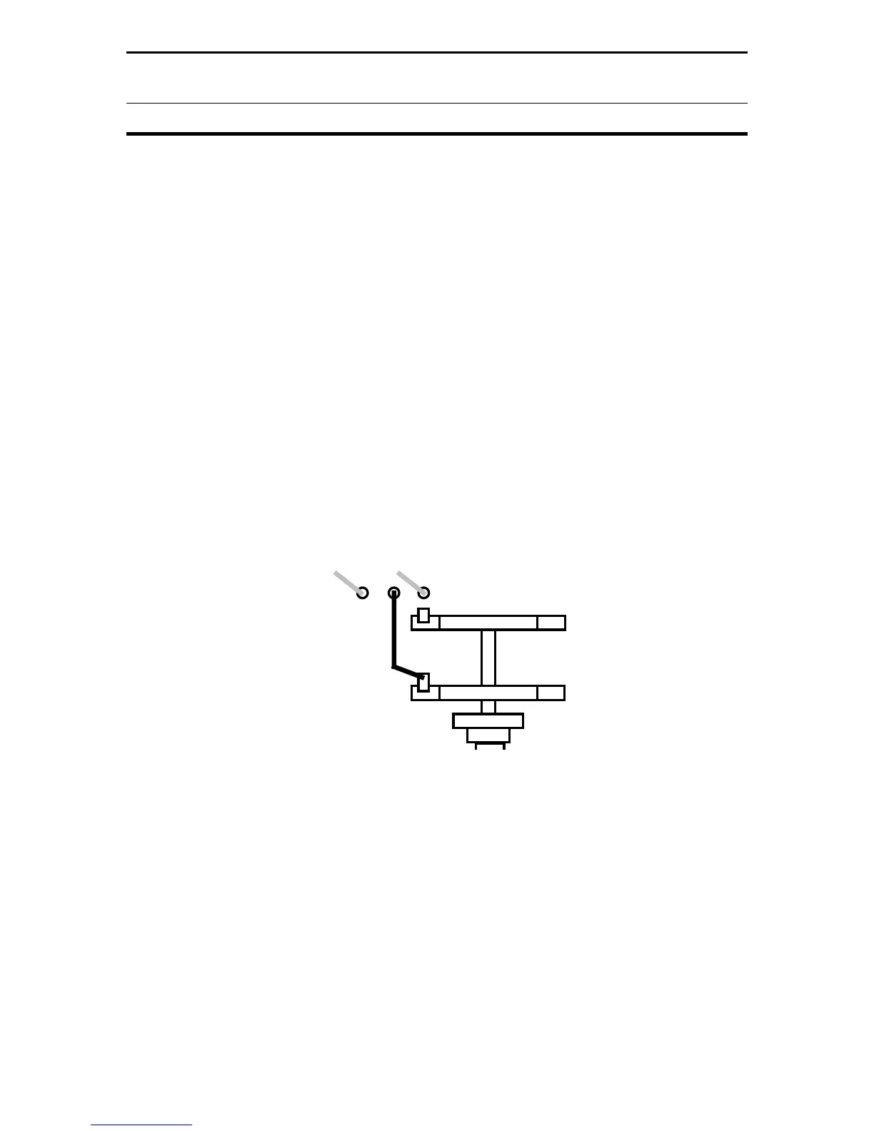
The sixth buss wire is connected between the pc board and a tab on SW4. Refer
to Diagram 3 below:
D/L
Wire
SW4
Connect
and Solder
Diagram 3: SW4 Tab Location
[ ] Install a buss wire at the unmarked hole between D/L and WIRE, and solder.
[ ] Locate the exposed solder tab on top of SW4's front wafer.
[ ] Route the buss wire to the designated terminal, install, and solder.
This completes circuit board sub-assembly. Note that several tuner models use
the same pc board and some parts locations are not used for this project. Before
moving on, take a few minutes to inspect and double-check your work.
 Loading...