MFJ-991B IntelliTuner Automatic Antenna Tuner Instruction Manual
2005-2012 MFJ Enterprises, Inc.
4
Note: When the tuner power is OFF, the tuner is bypassed and RF from the transmitter or
amplifier goes directly to the antenna with no matching. The MFJ-991B always powers
up in bypass mode to ensure maximum receiver sensitivity if you are listening on a
different frequency than where tuning last occurred. When tuning starts, the MFJ-991B
reverts to previously stored matching values or finds a new match if no previous
information is in memory. You may bypass the tuner at anytime when the tuner power is
ON by pressing [C-DN] and [L-DN] simultaneously or pressing [TUNE] quickly. When
the MFJ-991B is bypassed, the reflected meter needle bounces to the 20-watt mark while
the switches are pressed.
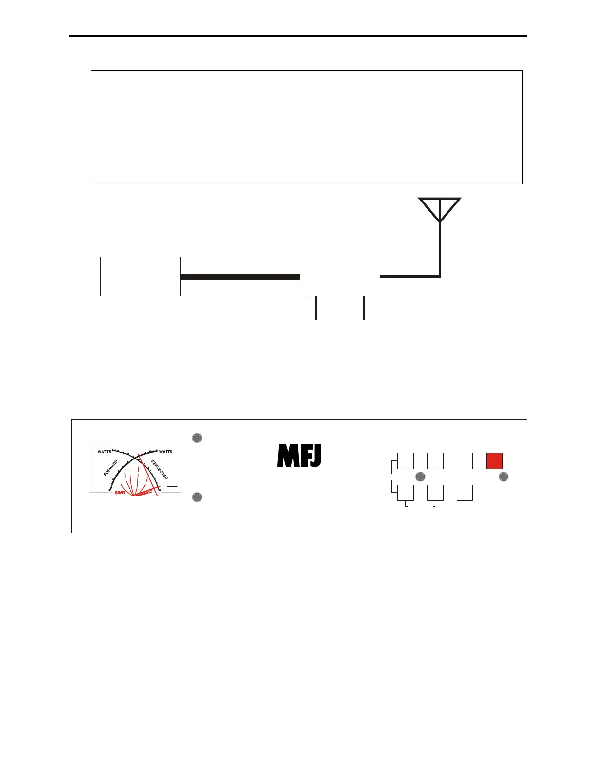
Transmitter
Automatic
Tuner
50-ohm Coax
Antenna
RF Ground 12 VD
Figure 1. Typical Installation Block Diagram.
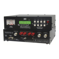
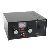
Front Panel
MODEL
MFJ-991B
C-UP L-UP AUTO POWER
C-DN L-DN TUNE
AUTOMATIC ANTENNA TUNER
Dual Power Level
300/150 Watts
MFJ IntelliTuner
TM
0
1
0
3
0
5
0
1
0
0
2
0
0
3
0
0
0
5
2
0
4
0
6
0
8
5
.
0
3.0
2.0
1
.
5
1
.
2
Hi x1
Lo
x.1
400-3083
1
1
0
Z
BYPASS
Figure 2. MFJ-991B Front Panel.
• SWR/Wattmeter: The cross-needle meter measures forward power, reflected power, and SWR. It
operates whenever the MFJ-991B is powered on. Full-scale readings are 300 watts forward and 60
watts reflected. The meter can be set to a low power range of 30 watts forward and 6 watts reflected,
or AUTO metering where the meter range is determined by the transmit power. The SWR is
measured at the point where the two needles cross. See “SWR/Wattmeter” on page 11 for more
detailed information.
• C-UP and C-DN Buttons: Used to manually increase or decrease the capacitance of the L-network
matching circuit. The capacitance range is 0 to 3900 pF. The upper limit of capacitance, dependent
on frequency, is restricted to limit the maximum voltage and current across the tuner’s components.
 Loading...