MFJ-1278B MULTI-MODE HARDWARE
MULTI-LEVEL INTERFACE CONNECTOR,J13
The MFJ-1278B provides the user with the capability to perform Multi-Level FAX
operations as well as Color SSTV work. Multi-Level FAX and Color SSTV operations are
accomplished through the addition of a Multi-Level Interface. The Multi-Level Interface
controls both transmit and receive operations for the Multi-Level FAX and Color SSTV
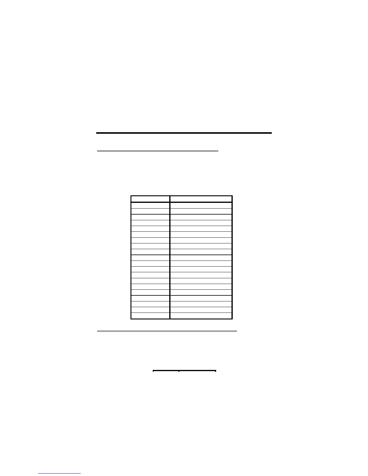
modes. Below in Table 8-4 are the pin outs for the ribbon cable connected at J13:
Table 8-4 J13 Pin Out
J13 Pin # Pin Function
1 No connection
2 No connection
3 Connect Tone Output
4 Ground
5 SSTV/FAX receive signals
6 153.6/307 KHz Clock Select
7 SSTV/FAX select
8 SSTV/FAX transmit tones
9 SSTV/FAX receive control
10 SSTV/FAX transmit control
11 -5 Volts
12 Data Bit 7
13 Data Bit 6
14 Data Bit 5
15 Data Bit 4
16 Data Bit 0
17 Data Bit 1
18 Data Bit 2
19 Data Bit 3
20 +5 Volts
EXTERNAL MODEM INTERFACE CONNECTOR - J14
The External Modem Interface Connector, J14 is available for easy and quick addition of the
MFJ-2400 or MFJ-9600 modems. The External Modem Interface Connector, J14 is a 5-pin
straight type header located just in front of the RS-232C serial port connector. Below in
Table 8-5, is the pin out of the External Modem Interface connector, J14:
Table 8-5 External Modem Interface Pin Out