EasyManuals Logo

MicaSense RedEdge User Manual

MicaSense RedEdge
12 pages
To Next Page IconTo Next Page
To Previous Page IconTo Previous Page
Page #9 background imageLoading...
Page #9 background image
PAGE 7
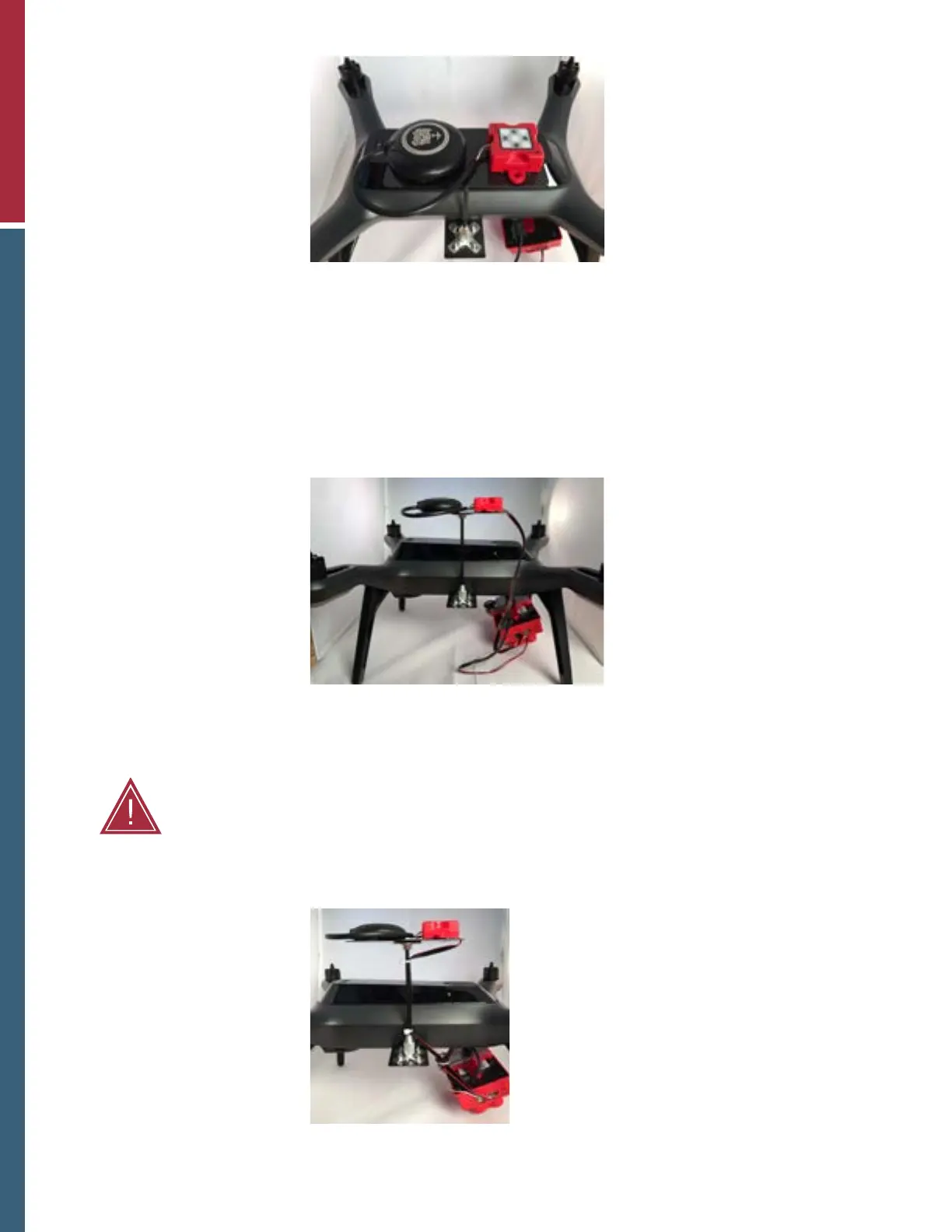
GPS and DLS mounted with VHB and connected
with their associated cables.
8. Connect the GPS unit to the DLS unit.
NOTE: See the RedEdge Integration Guide for more details.
9. Connect the long 6pin connector from the DLS “CAM” connector to the matching connector on
the RedEdge camera.
NOTE: See the RedEdge Integration Guide for more details.
6pin cable connected between the RedEdge and
DLS.
10. Using the zip ties, secure the wires to the mast and aircraft frame as necessary.
Completed integration.
11. Using scissors or something similar, trim the zip ties.
WARNING: Failure to properly secure loose wires may lead to interference with the aircraft
propellers. This may damage the Solo, RedEdge, or both.

Questions and Answers:

Question and Answer IconNeed help?

Do you have a question about the MicaSense RedEdge and is the answer not in the manual?

MicaSense RedEdge Specifications

General IconGeneral
Spectral BandsBlue, Green, Red, Red Edge, NIR
Band Central WavelengthBlue: 475nm, Green: 560nm, Red: 668nm, Red Edge: 717nm, Near Infrared: 840nm
BandwidthBlue: 20 nm, Green: 20 nm, Red: 10 nm, Red Edge: 10 nm
Image Resolution1280 x 960 pixels per band
Capture Rate1 capture per second
Field of View47.2° HFOV
Power Requirements7-25 V DC
Sensor5 individual sensors
InterfacesSerial, Ethernet
Operating Temperature0-50° C
Storage Temperature-20-60° C
DLSIntegrated Downwelling Light Sensor (DLS)
Sensor TypeGlobal Shutter CMOS

Related product manuals