SF52 User’s Manual
Michell Instruments 3
INSTALLATION
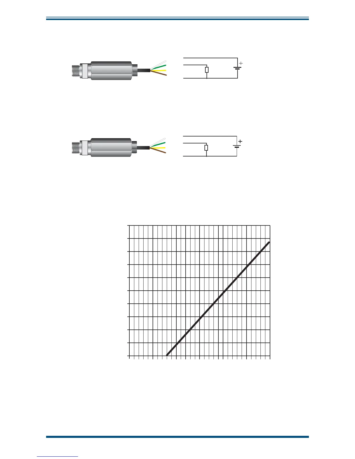
2.2 Electrical Schematic
White
Green
Yellow
(do not use)
Brown
Supply
14 to 30 V for 0 to 10 V output
8 to 30 V for 0 to 1 V output
Figure 2
Voltage 3-Wire Connections
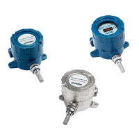
Supply
8 to 30 V for 4 - 20 mA output
White
Green
Max load
20 mA
Yellow
(do not use)
Brown
Figure 3
mA 3-Wire Connections
2.2.1 Electrical Boundaries mA 3-Wire
100
0
0 5 10 15 20 25 30
200
300
400
500
600
700
800
900
1000
Resistance (ohm)
Figure 4
Maximum Load of SF52 3-Wire mA - Including Cable Resistance