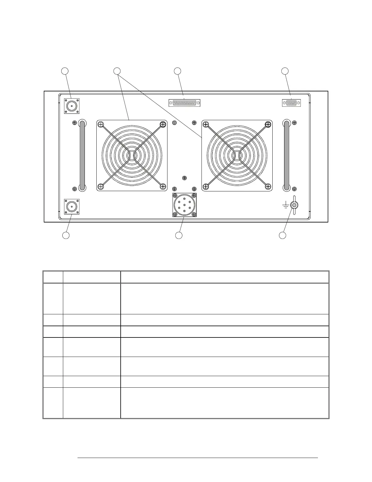
1 kW PA Rear Panel
Figure 10 identifies the items located on the rear panel of the 1 kW amplifier, and Table 6 explains
their functions.
EXCITER CONTROL MONITOR
RF Out
RF In
+48VDC
675
231
4
Figure 10. 1 kW PA Rear Panel
Table 6. 1 kW PA Rear Panel Items
Item Description Function
1 RF IN Connector N-type connector for RF connection to the RM125/RM125R:
• In the receive or bypass mode, serves as output for receive signals
• In the transmit mode, serves as input for RF drive signals
2 +48VDC connector
7-pin circular connector for connection to DC power source
3 Grounding screw Connection of ground to the 1 kW amplifier
4 MONITOR
connector
9-pin D-type female connector for connection to maintenance monitor (ASCII
terminal or PC with terminal emulation program)
5 EXCITER CONTROL
Connector
25-pin D-type female connector, contains the control interface that enables the
RM125/RM125R to control the 1 kW amplifier
6 Exhaust Vents Cooling air exhaust vents
7 RF OUT Connector N-type connector for RF connection to antenna system:
• In the receive or bypass mode, serves as input for receive signals
• In the transmit mode, serves as output for amplified RF signals
6888882V02 27