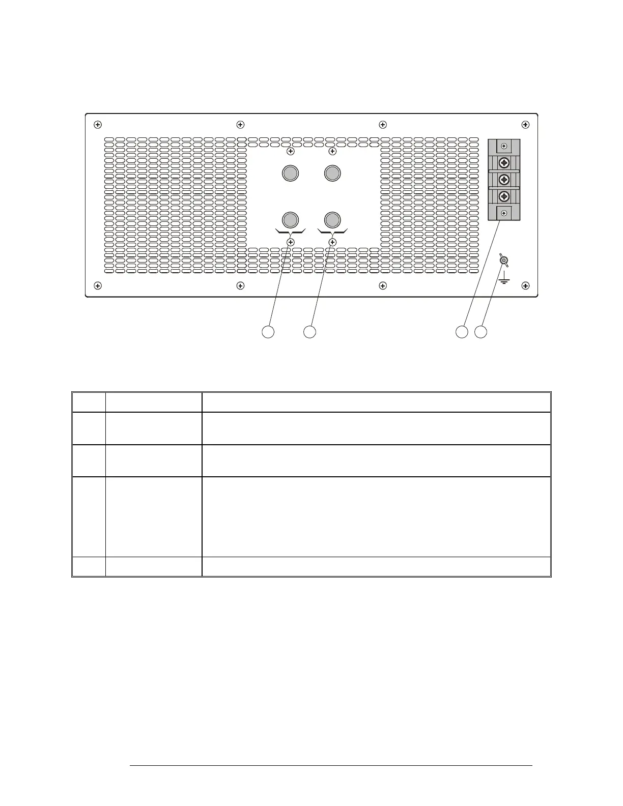
PS Rear Panel
Figure 12 identifies the items located on the front panel of the PS unit, and Table 8 explains their
functions.
OUT 1
+V +V
-V -V
45V
45V
OUT 2
GND
AC INPUT
110-230VAC/ 47~63Hz
L
N
G
DC OUTPUT
12 34
Figure 12. PS Rear Panel
Table 8. PS Rear Panel Items
Item Description Function
1 OUT 1 +V, -V
terminals
Output voltage terminals of power supply subsystem 1
2 OUT 2 +V, -V
terminals
Output voltage terminals of power supply subsystem 2
3 AC INPUT strip Terminal strip, covered by a protective cover, for connection to AC power
source:
• L – line (phase) terminal
• N – neutral terminal
• G – ground terminal
4 Grounding screw Connection of ground to the 1 kW amplifier
6888882V02 29