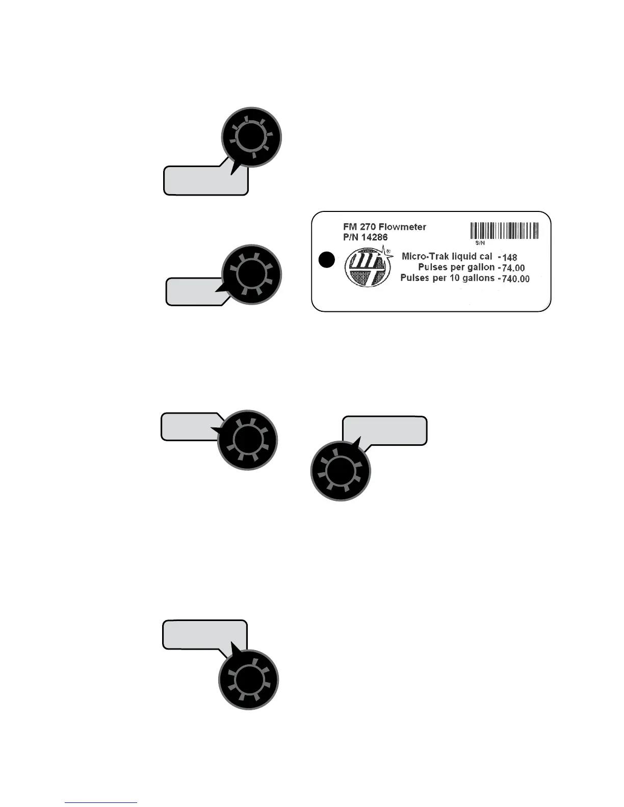
18
000000000
Your Micro-Trak flowmeter has been tested at the factory
and assigned a “FLOW CAL” value to make it operate
properly with the MT-3405F™ II console. This number
is printed on the plastic tag attached to the flowmeter.
See Illustration 13. This is a starting point only. If your
spray solution has a specific gravity or viscosity that is
different than water, flowmeter calibration should be done
for the specific solution (Please refer to Fine-Tuning Flow-
me ter Calibration in Appendix C on page 45.)
Illustration 13
Calibration (cont)
Entering Calibration Values (cont)
TARGET RATE: Enter the value for the desired target
application rate in gallons per acre (liters per
hectare) or lbs. of N per acre (kgs of N per
hectare). This is the application rate that the
console will lock onto when operating in
AUTO.
TARGET
RATE
RATE
ADJUST RATE: Enter the value for the desired amount of
change in gallons per acre (liters per hectare) to be used for
making on-the-go rate adjustments when
operating in AUTO. For example, if a value
“1.0” is entered, you will be able to increase
or decrease your
application rate in
one-gallon (liter) or
lb. (kg) increments
during operation in AUTO. To disable this feature, simply
enter “.0” for a val ue.
ADJUST
RATE
TANK
MIN FLOW: The pur pose of this calibration value is to
prevent the system from applying below the recommended
minimum rate for the nozzles. The minimum flow rate in
gallons per minute (li ters
per minute) based
on the nozzles being
used, for the en tire
boom on the sprayer.
DO NOT enter the actual flow of your spray
application. FOR EXAMPLE: If the min i mum
flow rate for the nozzle you are using is .22
GPM at their minimum recommended pres sure and your
boom has 20 nozzles, enter 4.4 as the MIN FLOW value (.22
x 20 = 4.4). The system WILL NOT ap ply at a rate lower than
this value when spraying in AUTO. This value should be
checked/ changed for each different nozzle that you use.
APPLICATION NOTE: Over-application may occur with
MIN FLOW set if ground speed is too slow.
MIN
FLOW
VOLUME /
MINUTE
FLOW CAL: This po si tion is used to cal i brate the flow me-
ter for ac cu rate liquid
mea sure ment. Enter
the Micro-Trak liquid
cal number printed on
the flowmeter tag (See
Il lus tra tion 7) The Flow
Cal number should not
be changed during
operation because a
change in the Flow Cal
number will also change some counter values.
FLOW
CAL
VOLUME
(1) (2) (3)
CAUTION: If spray lines are pressurized, nozzles may
spray during WIDTH calibration (below).
WIDTH:
Enter the effec tive working width, in inch es (meters)
for the boom section currently shown on the dis play. It is
simplest to start with all booms ON and then turn each boom
OFF, from left to right,
after calibrating the
width. Note that the
system must be in
RUN (not HOLD) to display boom numbers.
Repeat this procedure for each boom
sec tion. Enter a value of “0” (.000) for any
unused boom sec tions.
Your “working” width per boom section will be the number
of nozzles on the boom section times the nozzle spacing in
inches (mm). For example, if you have 7 nozzles spaced at 20
inches, the working width of the boom section is 140 inches.
WIDTH
CAL
AREA
(1) (2) (3)


 To Next Page