2006-2019 Microchip Technology Inc. DS30009711C-page 11
I/O Ports with PPS
4.3 Controlling Peripheral Pin Select
Peripheral Pin Select features are controlled through two sets of Special Function Registers
(SFRs): one to map peripheral inputs and one to map peripheral outputs. Because they are
separately controlled, a particular peripheral’s input and output (if the peripheral has both) can
be placed on any selectable function pin without constraint.
The association of a peripheral to a peripheral-selectable pin is handled in two different ways,
depending if an input or output is being mapped.
4.3.1 INPUT MAPPING
The inputs of the Peripheral Pin Select options are mapped on the basis of the peripheral; that
is, a bit field associated with a peripheral dictates the pin it will be mapped to. The RPINRx reg-
isters (refer to Register 4-3 and Table 4-1) contain sets of 6-bit fields, with each set associated
with one of the remappable peripherals. Programming a given peripheral’s bit field with an RPn
value maps the RPn pin to that peripheral. For any given device, the valid range of values for any
of the bit fields corresponds to the maximum number of Peripheral Pin Selections supported by
the device.
The peripheral inputs that support Peripheral Pin Selection have no default pins. Since the
implemented bit fields of RPINRx registers reset to all ‘1’s, the inputs are all tied to V
SS in the
device’s default (Reset) state.
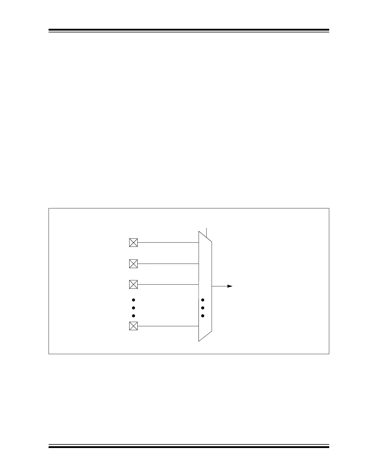
For example, assigning RPINR18<5:0> to 0x2 selects RP2 as the U1RX input. Figure 4-2
illustrates remappable pin selection for the U1RX input.
Figure 4-2: Remappable Input for U1RX
RP0
RP1
RP2
RPn
0
n
1
2
U1RX Input
U1RXR<5:0>
to Peripheral