dsPIC33/PIC24 Family Reference Manual
DS30009740B-page 10 2010-2013 Microchip Technology Inc.
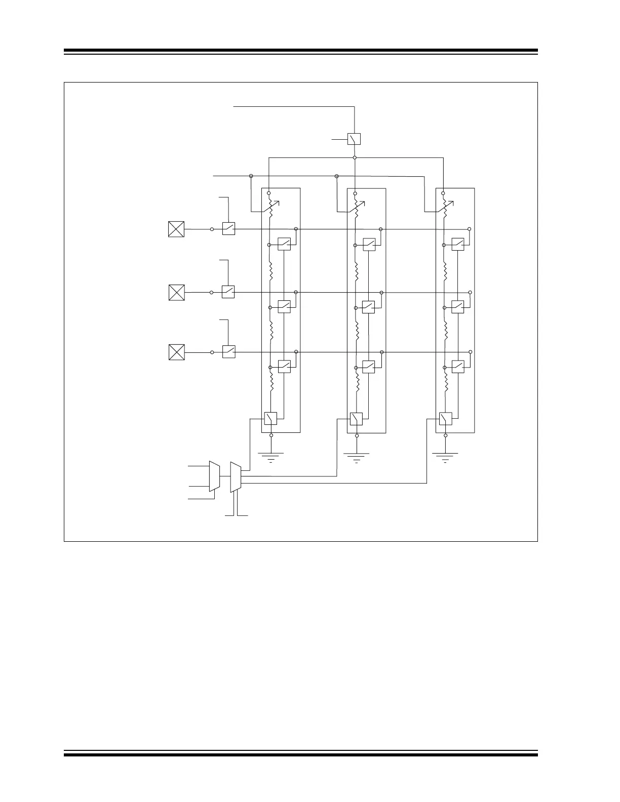
Figure 5-1: LCD Bias Internal Resistor Ladder Connection Diagram
There are two power modes, designated as “Mode A” and “Mode B”. Mode A is set by the bits,
LRLAP<1:0>, and Mode B by the LRLBP<1:0> bits. The resistor ladder to use for Modes A and
B are selected by the bits, LRLAP<1:0> and LRLBP<1:0>, respectively.
Each ladder has a matching contrast control ladder, tuned to the nominal resistance of the refer-
ence ladder. This contrast control resistor can be controlled by the LCDCST<2:0> bits
(LCDREF<13:11>). Disabling the internal reference ladder results in all of the ladders being
disconnected, allowing external voltages to be supplied.
To get additional current in High-Power mode, when LRLAP<1:0> (LCDREF<7:6>) = 11, both
the medium and high-power resistor ladders are activated.
Whenever the LCD module is inactive (LCDA (LCDPS<5>) = 0), the reference ladder will be
turned off.
LCDBIAS3
LCDBIAS2
LCDBIAS1
VLCD3PE
VLCD2PE
VLCD1PE
LCDCST<2:0>
LCDIRE
LRLAT<2:0>
A Power Mode
B Power Mode
LRLAP<1:0> LRLBP<1:0>
Low
Resistor
Ladder
Medium
Resistor
Ladder
High
Resistor
Ladder
VDD