2010-2013 Microchip Technology Inc. DS30009740B-page 11
Liquid Crystal Display (LCD)
5.1.1 AUTOMATIC POWER MODE SWITCHING
As an LCD segment is electrically only a capacitor, current is drawn only during the interval when
the voltage is switching. To minimize total device current, the LCD reference ladder can be oper-
ated in a different power mode for the transition portion of the duration. This is controlled by the
LCDREF register.
Mode A Power mode is active for a programmable time, beginning at the time when the LCD
segment waveform is transitioning. The LRLAT<2:0> (LCDREF<2:0>) bits select how long the
transition or if the Mode A is active. Mode B Power mode is active for the remaining time before
the segments or commons change again.
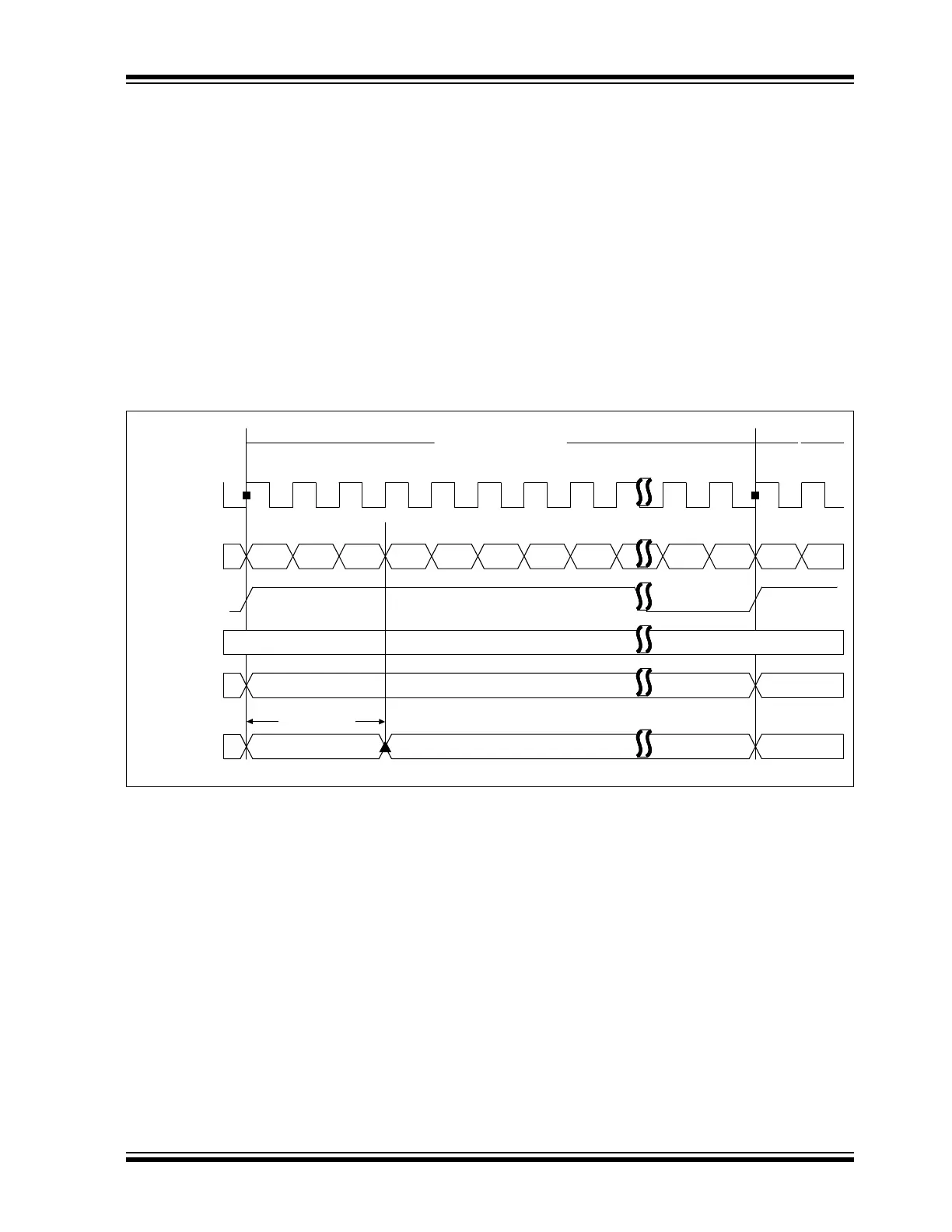
As shown in Figure 5-2, there are 32 counts in a single segment time. Type-A can be chosen
during the time when the waveform is in transition. Type-B can be used when the clock is stable
or not in transition.
By using this feature of automatic power switching using Type-A/Type-B, the power consumption
can be optimized for a given contrast.
Figure 5-2: LCD Reference Ladder Power Mode Switching Diagram
Single Segment Time
‘H00 ‘H01 ‘H02 ‘H03 ‘H04 ‘H05 ‘H06 ‘H07 ‘H1E ‘H1F ‘H00 ‘H01
‘H3
Power Mode A Power Mode B Mode A
LRLAT<2:0>
lcd_32x_clk
cnt<4:0>
lcd_clk
LRLAT<2:0>
Segment Data
Power Mode