2010-2013 Microchip Technology Inc. DS30009740B-page 13
Liquid Crystal Display (LCD)
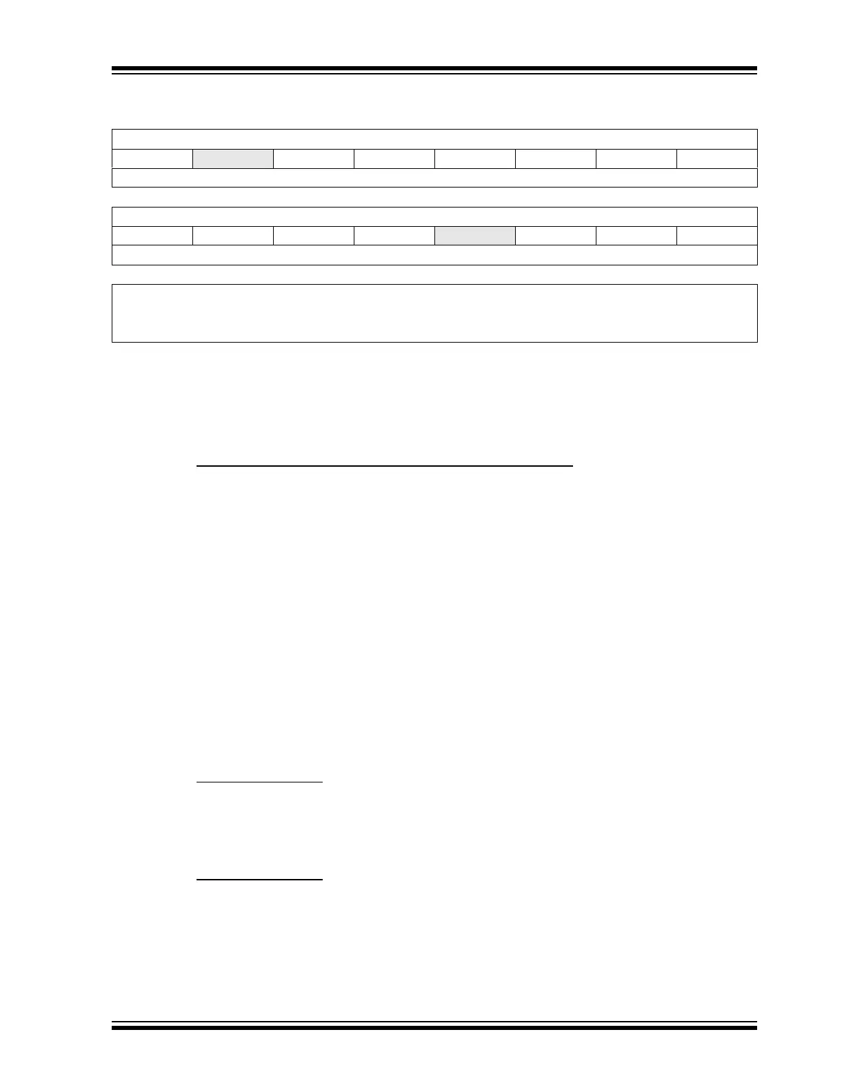
Register 5-1: LCDREF: LCD Reference Ladder Control Register
R/W-0 U-0 R/W-0 R/W-0 R/W-0 R/W-0 R/W-0 R/W-0
LCDIRE
— LCDCST2 LCDCST1 LCDCST0 VLCD3PE VLCD2PE VLCD1PE
bit 15 bit 8
R/W-0 R/W-0 R/W-0 R/W-0 U-0 R/W-0 R/W-0 R/W-0
LRLAP1 LRLAP0 LRLBP1 LRLBP0
— LRLAT2 LRLAT1 LRLAT0
bit 7 bit 0
Legend:
R = Readable bit W = Writable bit U = Unimplemented bit, read as ‘0’
-n = Value at POR ‘1’ = Bit is set ‘0’ = Bit is cleared x = Bit is unknown
bit 15 LCDIRE: LCD Internal Reference Enable bit
1 = Internal LCD reference is enabled and connected to the internal contrast control circuit
0 = Internal LCD reference is disabled
bit 14 Unimplemented: Read as ‘0’
bit 13-11 LCDCST<2:0>: LCD Contrast Control bits
Selects the Resistance of the LCD Contrast Control Resistor Ladder:
111 = Resistor ladder is at maximum resistance (minimum contrast)
110 = Resistor ladder is at 6/7th of maximum resistance
101 = Resistor ladder is at 5/7th of maximum resistance
100 = Resistor ladder is at 4/7th of maximum resistance
011 = Resistor ladder is at 3/7th of maximum resistance
010 = Resistor ladder is at 2/7th of maximum resistance
001 = Resistor ladder is at 1/7th of maximum resistance
000 = Minimum resistance (maximum contrast); resistor ladder is shorted
bit 10 VLCD3PE: LCD Bias 3 Pin Enable bit
1 = Bias 3 level is connected to the external pin, LCDBIAS3
0 = Bias 3 level is internal (internal resistor ladder)
bit 9 VLCD2PE: LCD Bias 2 Pin Enable bit
1 = Bias 2 level is connected to the external pin, LCDBIAS2
0 = Bias 2 level is internal (internal resistor ladder)
bit 8 VLCD1PE: LCD Bias 1 Pin Enable bit
1 = Bias 1 level is connected to the external pin, LCDBIAS1
0 = Bias 1 level is internal (internal resistor ladder)
bit 7-6 LRLAP<1:0>: LCD Reference Ladder A Time Power Control bits
During Time Interval A:
11 = Internal LCD reference ladder is powered in High-Power mode
10 = Internal LCD reference ladder is powered in Medium Power mode
01 = Internal LCD reference ladder is powered in Low-Power mode
00 = Internal LCD reference ladder is powered down and unconnected
bit 5-4 LRLBP<1:0>: LCD Reference Ladder B Time Power Control bits
During Time Interval B:
11 = Internal LCD reference ladder is powered in High-Power mode
10 = Internal LCD reference ladder is powered in Medium Power mode
01 = Internal LCD reference ladder is powered in Low-Power mode
00 = Internal LCD reference ladder is powered down and unconnected
bit 3 Unimplemented: Read as ‘0’