Case 2 – Connecting J-Link Probes to application board with IS2083BM
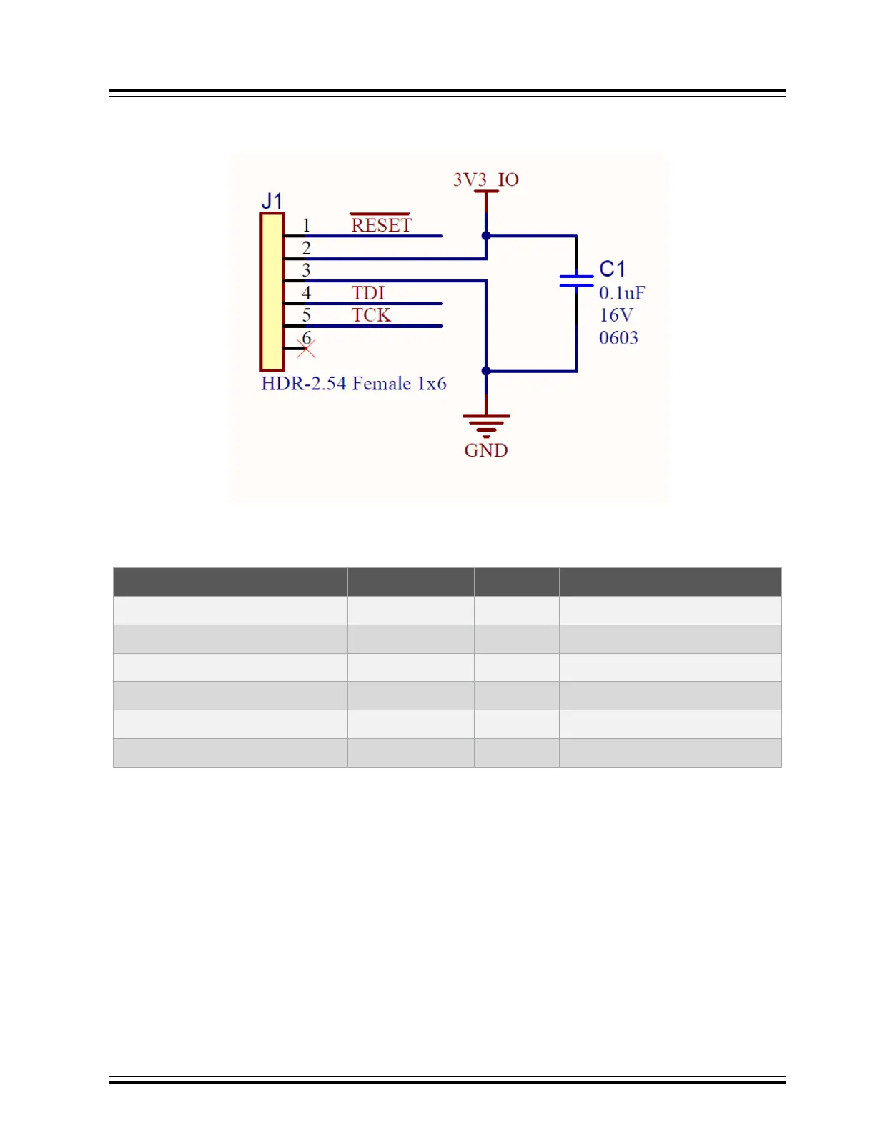
Figure 3-4. J-Link 6-pins connector schematic
Connect the following pins from your board to the 6pins connector:
Table 3-1. Pin details for the IS2083BM/BM83 board
J-Link 6pin Connector BM83 IS2083BM Description
Pin1 Pin43, RST_N RST_N Reset IS2083BM
Pin2 3V3 3V3_IO 3V3 power
Pin3 Ground Ground Ground
Pin4 Pin46, TDI_CPU TDI_CPU Data
Pin5 Pin47, TCK_CPU TCK_CPU Clock
Pin6 NC NC Not used
IS2083
Hardware Connection
© 2019 Microchip Technology Inc.
User Guide
DS50002892A-page 14