V.35
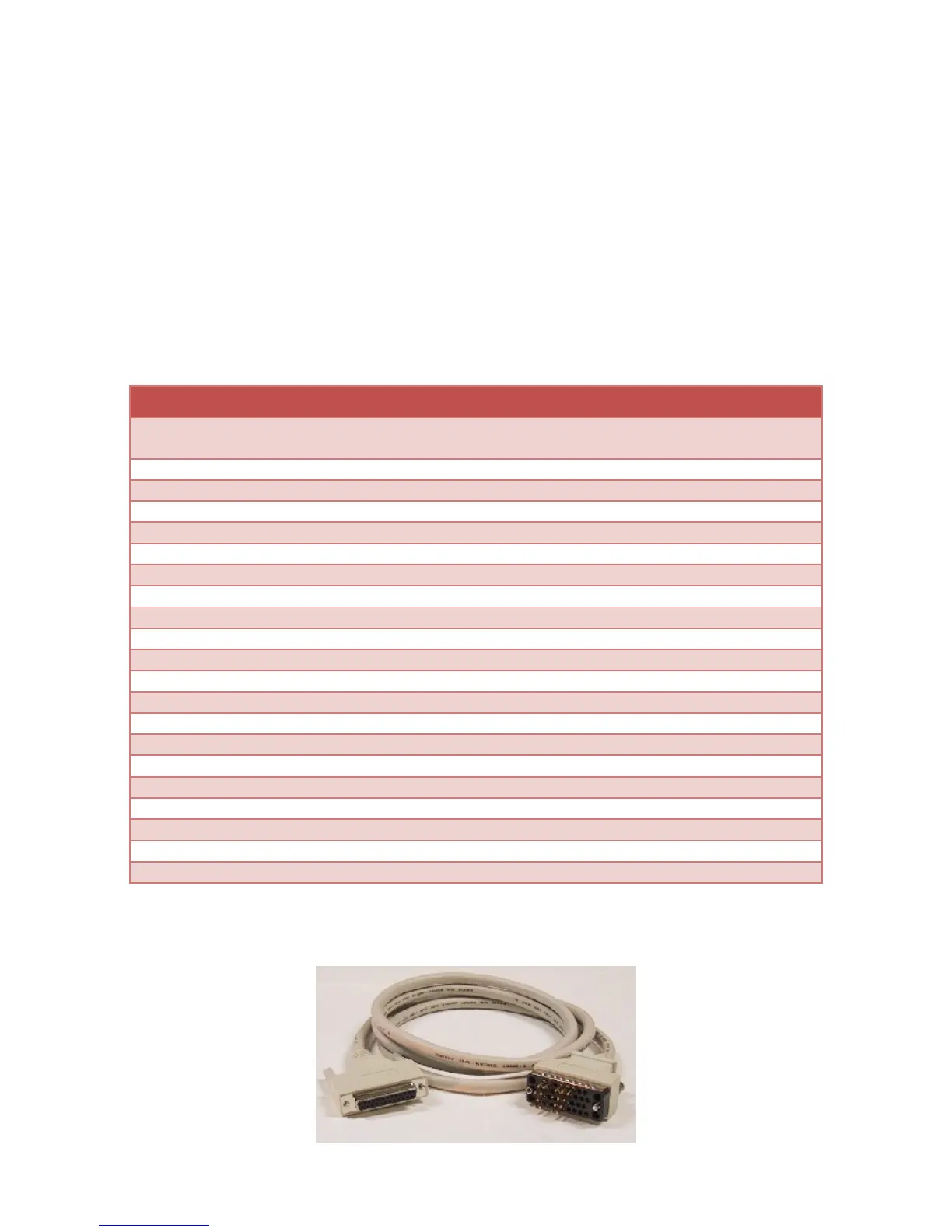
TheV.35standardusesamixofsingleendedanddifferentialsignalsona34pinblockconnector.Touse
thisstandard,installtheV.35jumpersontheportandusetheMicroGateV.35cable(Part#2534GT,
pictureshownbelow).
NotethattheLL,RL,andRIsignalsarea vailableontheadapter’sDB‐25connectorwhentheV.35
jumpersareinstalled,butarenotavailable(NC=noconnect)onthe34pinblockconnectorwhenusing
theV.35cable.
ThemaximumdataratesupportedbytheadapterwhenusingV.35is10Mbps.Cablelengthandsignal
loadingmayreducethemaximumusabl edataratefromthisvalue.
V.35MaleDTE
SignalName ElectricalDesc DB25
Pin#
V.35Block
Pin#
Direction
Earth/ShieldGround 1 A
TxD(+/A),TransmitData RS‐422/V.11 2 P Output
RxD(+/A),ReceiveData RS‐422/V.11 3 R Input
RTS,RequesttoSend RS‐232/V.28 4 C Output
CTS,CleartoSend RS‐232/V.28 5 D Input
DSR,DataSetReady RS‐232/V.28 6 E Input
SignalGround 7 B
DCD,DataCarrierDetect RS‐232/V.28 8 F Input
RxC(‐/B),ReceiveClock RS‐422/V.11 9 X Input
AuxClk(‐/B),DTEClockOutput RS‐422/V.11 11 W Output
TxC(‐/B),TransmitClock RS‐422/V.11 12 AA Input
TxD(‐/B),TransmitData RS‐422/V.11 14 S Output
TxC(+/A),TransmitClock RS‐422/V.11 15 Y Input
RxD(‐/B),ReceiveData RS‐422/V.11 16 T Input
RxC(+/A),ReceiveClock RS‐422/V.11 17 V Input
LL,LocalLoopbackControl RS‐232/V.28 18 NC Output
DTR,DataTerminalReady RS‐232/V.28 20 H Output
RL,RemoteLoopbackControl RS‐232/V.28 21 NC Output
RI,RingIndicator RS‐232/V.28 22 NC Input
AuxClk(+/A),DTEClockOutput RS‐422/V.11 24 24 Output
Figure6 V.35Cable(Part#2534GT)