V.35
The V.35 standard uses a mix of single ended and differential signals on a 34-pin block connector. To use
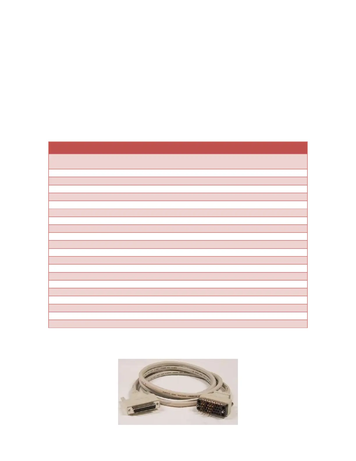
this standard, select V.35 in software and use the MicroGate V.35 cable (Part # 2534GT, picture shown
below).
Note that the LL, RL, and RI signals are available on the adapter’s DB-25 connector when the V.35
interface is selected, but are not available (NC = no connect) on the 34-pin block connector when using
the V.35 cable.
The maximum data rate supported by the adapter when using V.35 is 10Mbps. Cable length and signal
loading may reduce the maximum usable data rate from this value.
AuxClk (+/B), DTE Clock Output
TxC (+/B), Transmit Clock
TxC (-/A), Transmit Clock
LL, Local Loopback Control
RL, Remote Loopback Control
AuxClk (-/A), DTE Clock Output
Figure 2 V.35 Cable (Part# 2534GT)