EasyManua.ls Logo

Microgate SyncLink USB - SyncLink USB Connector Pin Assignments; RS-232 Connector Pinout

Microgate SyncLink USB
17 pages
Print Icon
To Next Page IconTo Next Page
To Previous Page IconTo Previous Page
Loading...
Serial Connector Pin Assignments
The assignment of signals to the connector pins is controlled by the software interface selection. For
interface types that use a connector different than DB-25 an adapter cable purchased from MicroGate is
required. The following sections describe the software settings and cables for each supported standard.
RS-232
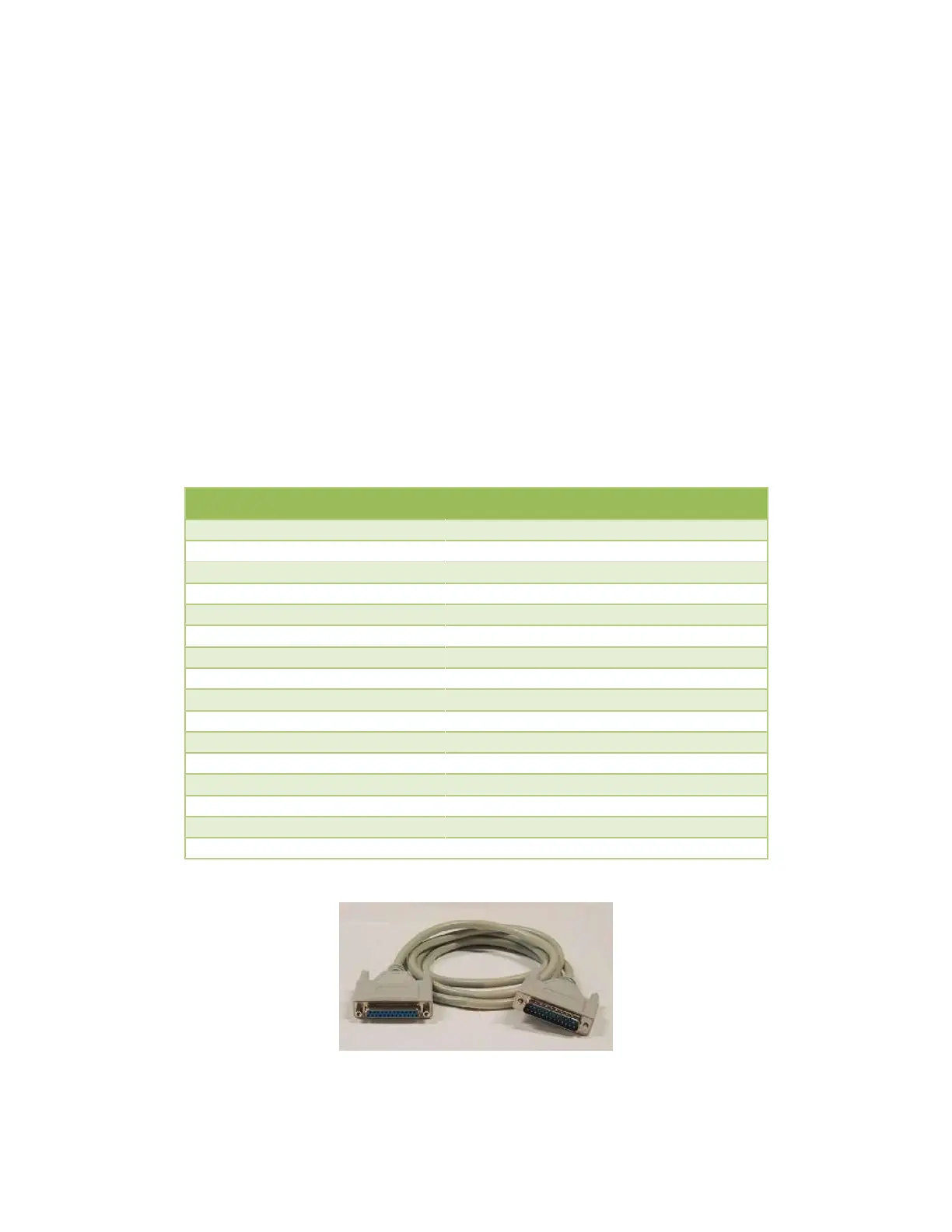
The RS-232 standard uses single ended signals on a DB-25 connector. The adapter DB-25 connector
follows this standard when the software selects RS-232. Use any straight through 25 conductor DB-25M
to DB-25F cable (such as MicroGate Part # CMF000) to connect the adapter connector to the
communications equipment.
The maximum data rate supported by the adapter when using RS-232 is 128Kbps. Cable length and
signal loading may reduce the maximum usable data rate from this value.
RS-232 DB-25 Male DTE
Signal Name
Electrical Desc
Pin #
Direction
Earth/Shield Ground
1
TxD, Transmit Data
RS-232/V.28
2
Output
RxD, Receive Data
RS-232/V.28
3
Input
RTS, Request to Send
RS-232/V.28
4
Output
CTS, Clear to Send
RS-232/V.28
5
Input
DSR, Data Set Ready
RS-232/V.28
6
Input
Signal Ground
7
DCD, Data Carrier Detect
RS-232/V.28
8
Input
TxC, Transmit Clock
RS-232/V.28
15
Input
RxC, Receive Clock
RS-232/V.28
17
Input
LL, Local Loopback Control
RS-232/V.28
18
Output
DTR, Data Terminal Ready
RS-232/V.28
20
Output
RL, Remote Loopback Control
RS-232/V.28
21
Output
RI, Ring Indicator
RS-232/V.28
22
Input
AuxClk, DTE Clock Output
RS-232/V.28
24
Output
Figure 1 RS-232 Cable (Part# CMF000)

Related product manuals