RS-422/RS-449/RS-485/RS-530
The RS-422 and RS-485 standards describe differential electrical signals but not connector or pin
assignments. The RS-530 and RS-449 standards define specific connectors and pin assignments using
differential signals. The differential signals on the card meet both RS-422 and RS-485 electrical
specifications.
RS-530 uses differential signals on a DB-25 connector. The adapter DB-25 connector follows this
standard when software selects RS-422/485. Use any straight through 25 conductor DB-25M to DB-25F
cable (such as MicroGate Part # CMF000) to connect the adapter to RS-530 communications equipment.
RS-449 uses differential signals on a DB-37 connector. To use this standard, select RS-422/485 in
software and use the MicroGate RS-449 cable (Part # 2537FM).
The maximum data rate supported by the adapter when using RS-530 or RS-449 is 10Mbps. Cable length
and signal loading may reduce the maximum usable data rate from this value.
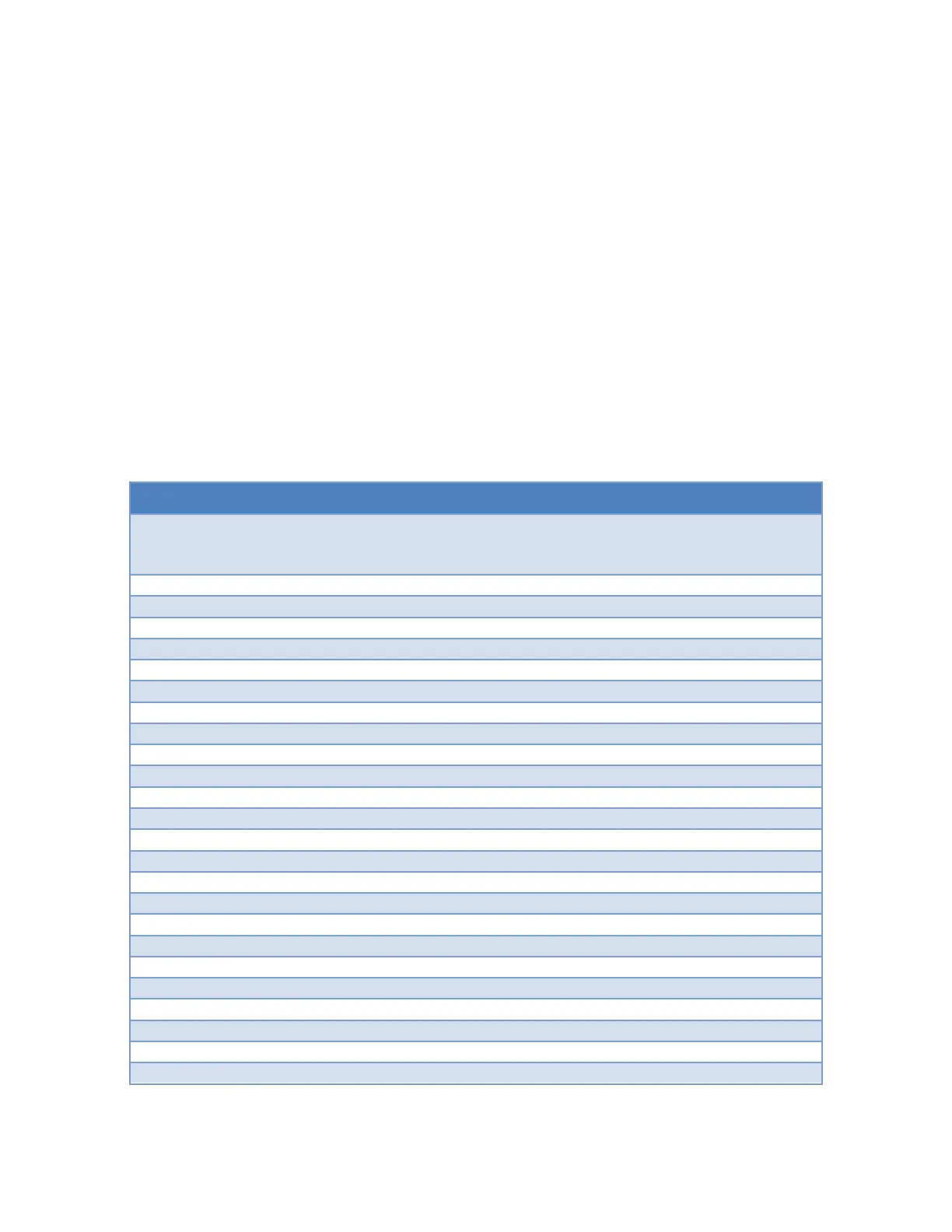
RS-422/RS-530/RS-449 Male DTE
RTS (-/A), Request to Send
DSR (-/A), Data Set Ready
DCD (-/A), Data Carrier Detect
DCD (+/B), Data Carrier Detect
AuxClk (+/B), DTE Clock Output
TxC (+/B), Transmit Clock
TxC (-/A), Transmit Clock
LL, Local Loopback Control
RTS (+/B), Request to Send
DTR (-/A), Data Terminal Ready
RL, Remote Loopback Control
DSR (+/B), Data Set Ready
DTR (+/B), Data Terminal Ready
AuxClk (-/A), DTE Clock Output