General Purpose I/O Signals
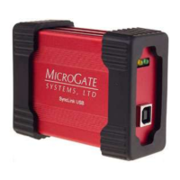
The SyncLink USB has a 24-pin header (2 x 12 pins, 0.050” spacing) inside the case and on the circuit
board that provides general-purpose input/output (GPIO) signals for application specific uses. These
signals are controlled by an application using the serial API (Windows and Linux). Each signal can be
configured to be either an input or an output. Inputs can be monitored and outputs can be controlled.
DC GPIO Specifications
Vil (input low) = -0.5V min, 0.8V max
Vih (input high) = 2.0V min, 5.5V max
Vol (output low) = 0.4V max
Voh (output high) = 2.4V min
Iol (output low) = 24mA max
Iil (output high) = -24mA max
Input Current = +/- 10uA max
GPIO signals are 3.3V TTL compatible and inputs are 5V tolerant.