The SyncLink USB adapter has a total of 20 general purpose I/O signals (GPIO[0] to GPIO[19]). By default
on power up all GPIO signals are configured as inputs (direction control = 0). Refer to the serial API
documentation for details on configuring and using GPIO signals.
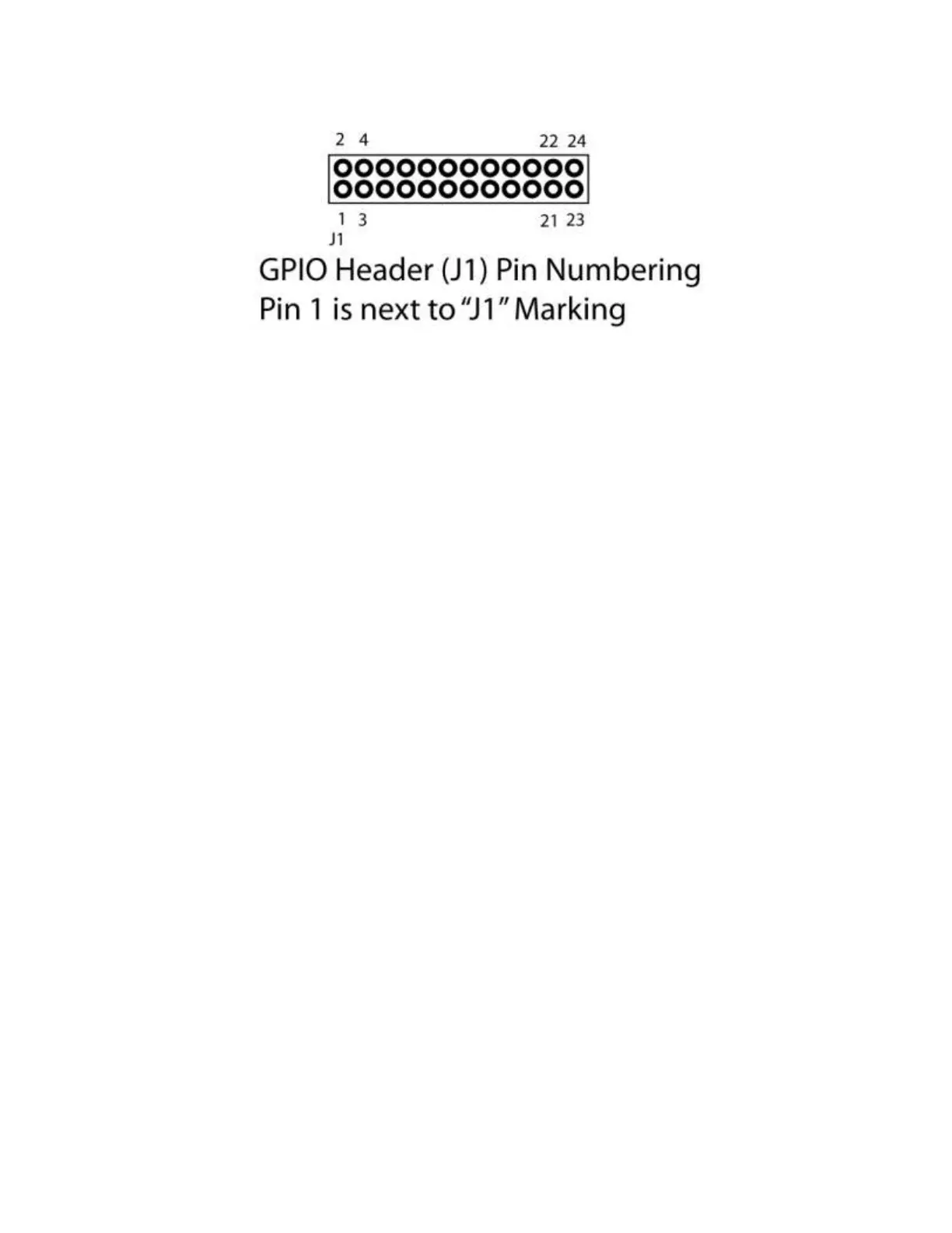
The GPIO header is not accessible from outside the standard case. For prototyping, the header can be
accessed by removing the case end plate from the USB connector end of the case. This allows space for
a ribbon cable to run to the outside of the case. For production, contact MicroGate for a quote on
custom end plates and connectors.
WARNING: Take care when connecting to GPIO signals to prevent damage to the serial adapter. Outputs
should only be connected to inputs and not other outputs. Voltage limits as shown above should not be
exceeded.