Rotary Microtome HM 340 E
MICROM International GmbH
Robert-Bosch-Str. 49
D- 69190 Walldorf 386 200 - English
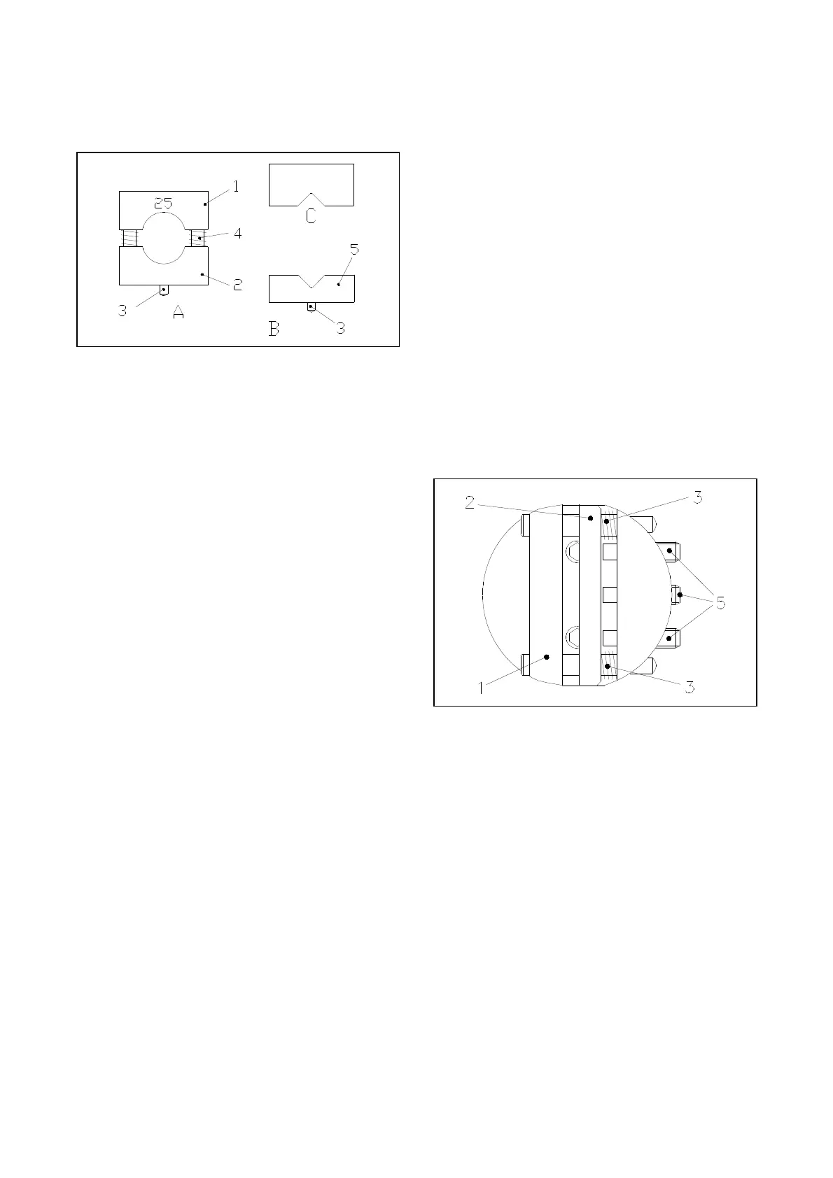
2-10-3 INSERT FOR ROUND SPECIMENS,
V-INSERT AND V-DISTANCE PIECE
Fig. 9
To cut round specimens, the insert for round
specimens (fig. 9 A) with defined diameters of 6,
15 and 25 mm (special sizes on request), the V-
insert (fig. 9 B) or the V-distance piece (fig. 9 C)
can be clamped into the standard specimen clamp.
The pin (fig. 9.3), which fits into the lower
clamping jaws (fig. 8.1), positions the insert
precisely. The two springs (fig. 9.4) make it easy
to remove the specimen from the inserts (fig. 9.1
and 9.2).
To insert the V-distance piece (9 C) against the
fixed jaw (fig. 8.2) of the standard specimen
clamp, first unscrew the knob and pull the spindle
out of the clamp. After having inserted the V-
distance piece, put in the spindle and turn the knob
(fig. 8.3) on the spindle.
2-10-4 FOIL CLAMP
The foil clamp (fig. 10) is a clamping system for
foils or thin specimens. To insert the specimen,
loosen the three clamping screws (fig. 10.5)
slightly and push the movable jaw (fig. 10.2)
sideways against the two springs (fig. 10.3). The
specimen is kept in place by the springs. For a new
alignment its position can be changed. Turn the
three clamping screws (fig. 10.5) to clamp the
specimen tightly.
When using an orienting adapter with the
instrument, first insert the enclosed graduated ring
into the orienting adapter by means of the pin.
With the graduated ring the orientation in X-/Y-
direction is annulled. However, it is possible to
turn in Z-axis 60° in either direction. Then mount
the foil clamp.
Fig. 10
According to the various specimens, it might be
helpful to use in addition MICROM's sandwich
supporting material (cat. no. 176010) on the right
and left side between specimen and clamping jaw.