Rotary Microtome HM 340 E
MICROM International GmbH
Robert-Bosch-Str. 49
D- 69190 Walldorf 386 200 - English
PART 2 OPERATING INSTRUCTIONS
2-1 SETTING UP THE MICROTOME
Unpack the microtome and remove the wrapping.
On the lower side of the instrument towards the
front and rear longitudinal axis, there are recessed
grips to lift or carry the microtome. Do not
transport the instrument on the handle of the
handwheel!
The microtome should be placed on a stable and
vibration free table as sectioning can be influenced
by nearby instruments which generate vibrations.
Take the section waste tray, which is separately
packed, and install it at the front of the base plate
(fig. 5.2).
To move the unit on the table, lift the base slightly
at the front end only and slide it.
NOTE! Remove the section waste tray to move or
carry the instrument. The section waste tray can be
pulled out of its proper position.
2-2 INITIAL TURN-ON
CAUTION! Before turning on the instrument for
the first time, please check if the power
requirements indicated on the type plate
correspond to the power supply voltage being
used.
The operating panel, which is separately packed,
can be attached to the instrument (fig. 5.1) or used
freestanding. Firstly, connect the operating panel
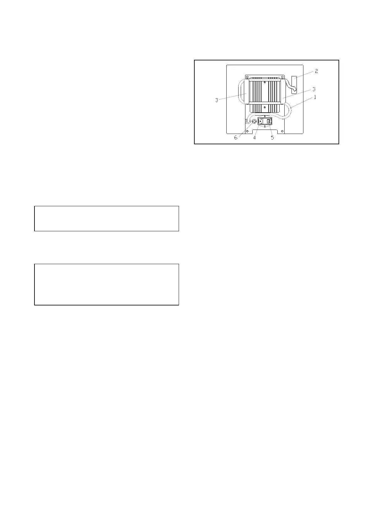
with the instrument. A 37-lead control cable (fig.
2.1) is fixed on the back of the instrument.
Connect this cable with the connector at the back
of the operating panel.
Should the operating panel be attached to the
instrument, push the 37-lead connector through the
corresponding hole (fig. 2.2) on the back of the
microtome. Turn the connector 90° and push it
through the hole on the front of the instrument.
Plug the connector into the operating panel. Fasten
the cable on the panel with the two screws. To
clear away the cable, insert it into the
corresponding holders (fig. 2.3) on the back of the
microtome.
Fig. 2
Connect the power cord to the power socket (fig.
2.4) on the back of the instrument. Turn on the
power switch (fig. 2.5).
Then, the specimen holder moves to the back end
position. This movement is always carried out
when the instrument is turned on. This way, the
instrument is calibrated.
Afterwards, FEED and TRIM are shown in the
second line of the display.
The insert for the two fuses is placed beside the
power switch.
(Exchange of fuses, see part 5).
The terms shown on the display are availabe in
English, German and French. If desired, the user
can change the language. (See 2-9, selecting the
indicated language).
 Loading...