Running the Demo Design With the MPM GUI
11
Running the Demo Design With the MPM GUI
I
2
C Setup
Use the MPM GUI to connect to the MPM target via I
2
C with the included Devantech/Robot Electronics USB-ISS
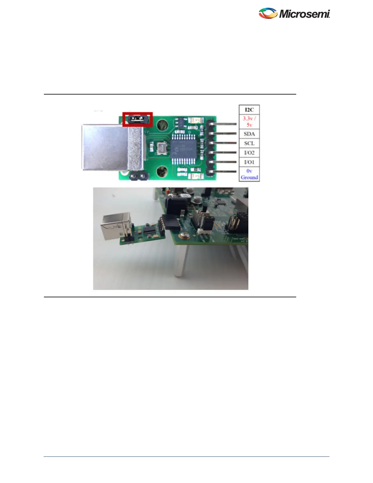
communications module. Ensure that the USB-ISS Power Link has a jumper removed for 3.3 V operations for
compatibility with the MPM target.
Remove Jumper on the USB-l2C Module, as shown in Figure 12.
The SF2-DMPM-DB Rev B boards have a dedicated connector for the Devantech USB Adaptor (J25).
Use the included standard USB A/B cable to connect the USB-ISS to your PC. Install the drivers that are bundled with
the MPM GUI in the C:\Microsemi\SF2_MPM_RefDesign_v6.1\Devantech_USB-ISS_drivers folder.
After installing the drivers, and plugging the USB-ISS module into a spare USB port, find which COM port it has been
assigned to. This will vary from system-to-system depending on how many COM ports you currently have installed. To
find out where it is, right-click on your Computer desktop icon and select Properties > Device Manager. Scroll down
and open the Ports (COM & LPT) tab. The USB serial port COM5 is listed, as shown in Figure 13 on page 12.
Figure 12 • SF2-DMPM-DB Rev B Slave l
2
C Connection