7
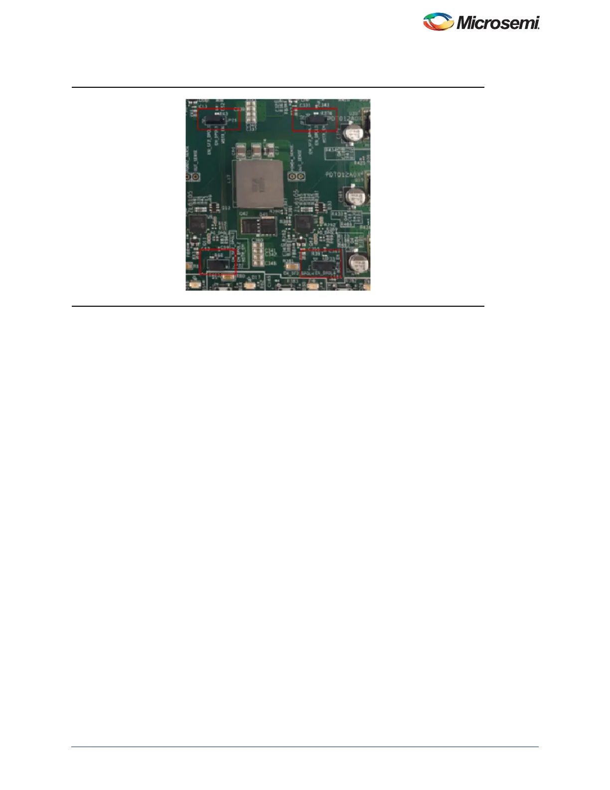
For the DPOLs on the SF2-DMPM-DB board JP21, JP22, JP32, and JP33 must be jumpered on pins 1 and 2 to route
the regulator enables of the first four DPOLs to the FMC connector, refer to Figure 7.
Programming the MPM
The first time you use the MPM, you need to use the MPM GUI to program the MPM design to the target hardware.
• For the SmartFusion2 Development Kit Board:
– Connect the 12 V/6 A power supply to the J18 12 V INPUT SUPPLY connector
– Connect FlashPro4 programmer to the J59 – FP4 Header
– Connect a mini USB cable between your PC and the FlashPro4
– Power the board on using SW7
• To run the MPM GUI:
–Select Data > FlashPro > Choose STAPL template and select the appropriate STAPL file for your target
hardware from the C:\Microsemi\SF2_MPM_RefDesign_v6.1\template folder.*
–Select Data > FlashPro > FlashPro Setup and browse to select the FlashPro software executable in your
Libero SoC v11 or later installation.
–Select Data > FlashPro > Write NVM & Fabric and the MPM GUI will launch FlashPro and program the full
design (MSS configuration, MPM firmware, MPM configuration data in ENVM along with the FPGA fabric
logic) to the target hardware. You will see a Command Shell “DOS Box” appear reporting progress. When
prompted you can close this. At this stage the MPM target should be programmed with the MPM reference
design.
• Power off the SmartFusion2 Development board by flipping SW7 to OFF and disconnecting the USB cable
and power supply cables
• Connect the SF2-DMPM-DB to the SmartFusion2 Development Kit board by connecting their respective
FMC connectors
• Connect the 12 V/5 A power supply to the SF2-DMPM-DB J1 12 V DC IN connector
• Reconnect the power cable to the SmartFusion2 Development Kit and turn SW7 to ON
• Power the SF2-DMPM-DB on by using SW2
• Reset the SmartFusion2 Development board by pressing SW9 RESET
Note: The power up order is important and it is advised to reset the system using SW9 on the SmartFusion2
Development Kit after powering up.
*See the Microsoft MSDN article for more on path length issues:http://msdn.microsoft.com/en-us/library/aa365247.aspx.
Figure 7 • DPOLs to the FMC Connector