Using the MPM
6
JP23 should have pins 1 and 2 jumpered and J24 should be jumpered to provide 3.3 V and 2.5 V supplies to the SF2-
DMPM-DB board from the FMC connector.
J22 should have 7 x 3 jumpers installed as shown in Figure 5 above, to link the eight DPOLs to PMBUS1. The last pair
of pins labeled PMBUS2 are unjumpered.
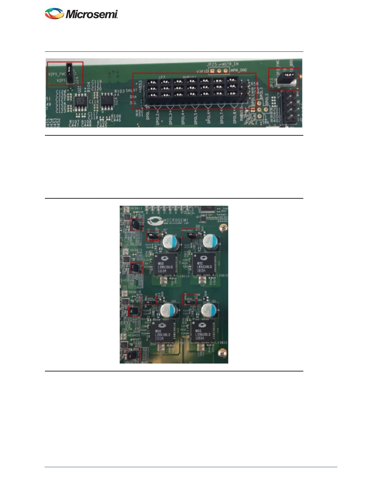
For the APOLs on the SF2-DMPM-DB JP3, JP26, JP27, JP28, JP2, JP29, JP30, and JP31 must be jumpered to
enable trimming, refer to Figure 6.
Figure 5 • SF2-DMPM-DB l
2
C Jumpers
Figure 6 • APOLs Jumpered to Enable Trimming