11
OM 1364
WWW.DAIKINAPPLIED.COM
SEqUENCE OF OPERATION
3-way valve will close and the fan will either shut o (fan switch
”AUTO”) or continue to run (fan switch “ON” or conguration
switch SW2 is OFF). When entering loop water temperature is
below 90°F, standard heating operation resumes.
Smart Dehumidication (Hot Gas Reheat)
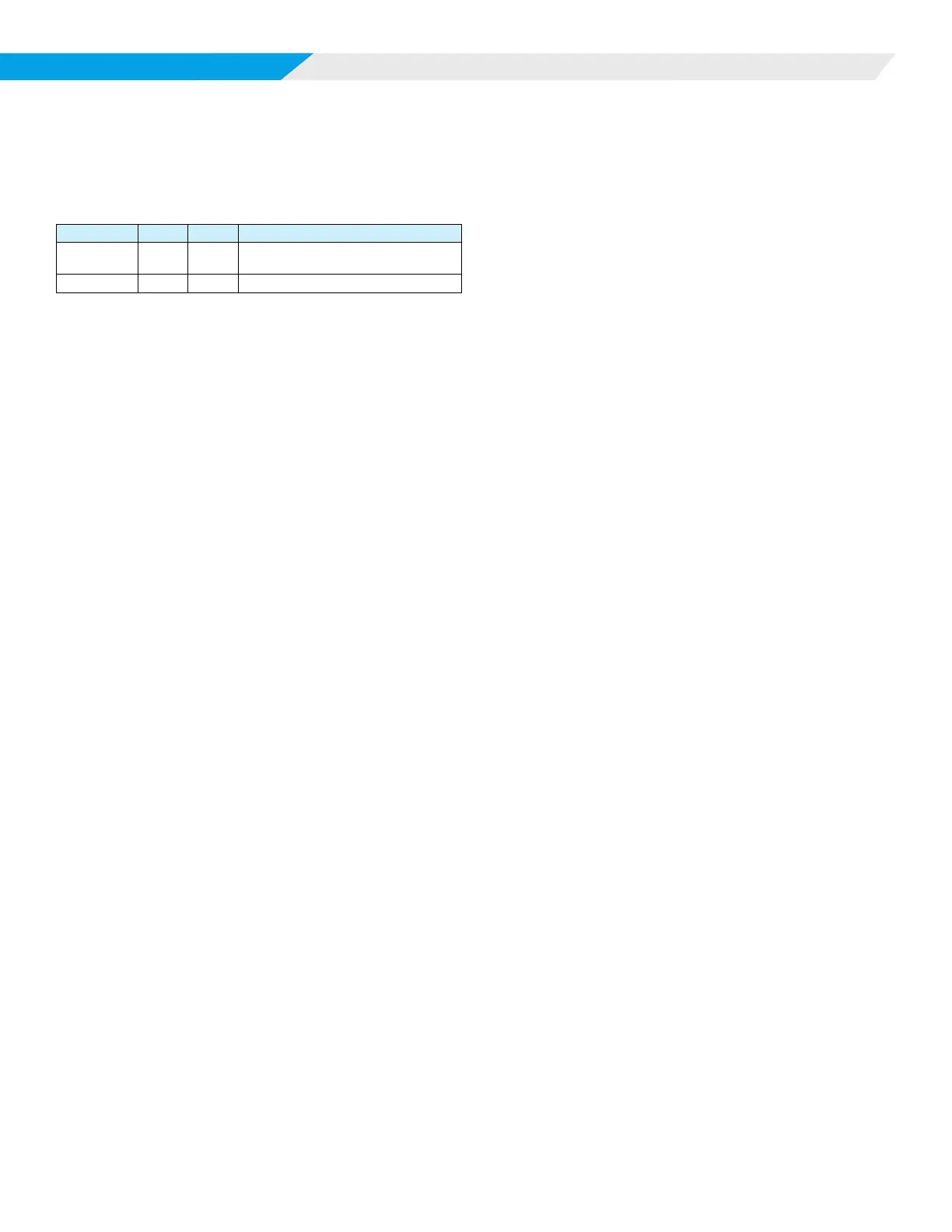
LED Activity Type Color Description
1 Flash Mode Green
No Call for Heating/Cooling/
Dehumidication
6 Flash Mode Green Call for Dehumidication
This mode requires optional hot gas reheat and a humidistat
input to the MT2310 I/O expansion module. This option also
utilizes airow management. If the space cooling temperature
setpoint is satised, but the humidity is above the space humidity
setpoint, the dehumidication mode is activated. The return air
temperature must be 68°F or greater.
On a call for smart dehumidication, the fan will energize at its
fan only setting, the pump will energize. After the 60 second
ow timer and the compressor minimum o timer expire (360
seconds), the fan will operate at the dehumidication setting, the
compressor will energize at full load operation and the hot gas
reheat valve will open, sending hot gas to the reheat coil. The
return air is cooled and reheated to near space temperature.
When the space humidity setpoint is satised the compressor will
turn o and the fan will operate according to its fan setting.
During smart dehumidication operation, a call for cooling will
close the hot gas reheat valve and the unit will resume normal
cooling operation until the space temperature is satised.
Simplied Dehumidication (Thermostat
control only)
This mode helps control space humidity by reducing the CFM
as the space temperature approaches the thermostat cooling
setpoint without hot gas reheat. The return air temperature
must be 68°F or greater for 1st stage operation. A multi-stage
thermostat is used to provide compressor cooling with multiple
airows. Using a 3 cooling stage thermostat the following occurs:
On a call for 1st stage cooling (Terminal TB1-3, HST on the
MT2310 I/O expansion module), the H6 output on the MT2300
board enables the pump or motorized valve to direct water ow
through the coaxial heat exchanger. The fan starts immediately
(unless it is already on) at the dehumidication CFM. If the return
air temperature is 68°F or greater, the compressor starts after the
60 second ow timer and the 360 second compressor minimum
o timer has expired. The compressor minimum on timer of 180
seconds starts. On a call for cooling, stage 2 (Terminal Y1), the
fan output will increase to the cooling stage 1 CFM. On a call for
cooling, stage 3 (Terminal Y2), the fan output will increase to the
cooling stage 2 CFM. The unit attempts to satisfy cooling at the
lowest possible CFM for maximum dehumidication. When the
room setpoint conditions are satised, the compressor will shut
o and the fan will either shut o (fan switch “AUTO”) or continue
to run (fan switch “ON” or conguration switch SW2 is OFF).
Humidistat Controlled Dehumidication
This mode helps control space humidity by using space humidity
sensing and by reducing the CFM by use of a humidistat in lieu of
a thermostat. The humidistat control replaces stage 1 thermostat
control as described above in simplied dehumidication
operation. The TB1-3, HST terminal is controlled by the
humidistat enabling dehumidication fan speed with compressor
operation. The return air temperature must be 68°F or greater.
Waterside Economizer
This mode requires the optional factory-installed waterside
economizer. A hydronic economizer coil, 3-way motorized valve
and a entering water temperature (EWT) sensor are added to the
unit.
For single stage SmartSource units with WSE
option
Hydronic cooling operation is adjustable between 50°F and 70°F
via BACnet or LON communication (factory default of 65°F).
• On a call from Y1 or cooling stage 1 setpoint, and the EWT
is below the hydronic cooling setpoint, but above 45°F, the
unit will operate in hydronic cooling mode. (The 3-way valve
is energized and the fan operates at the hydronic cooling
CFM setting).
• On a call from Y2 of the thermostat or second stage cooling
setpoint, and the EWT is below the hydronic cooling
setpoint, but above 45°F, the unit will operate in hydronic
cooling mode and full load mechanical cooling. (The fan will
operate at the full load cooling CFM).
If at any time the EWT rises above the entering water
temperature setpoint plus 5°F (while operating) or below 45°F,
the 3-way valve will de-energize, disabling WSE operation.
If WSE is not available due to entering water temperatures out of
range, the sequence becomes:
• On a call from Y1 or cooling stage 1 setpoint, the unit
operates at full load mechanical cooling. (The fan will
operate at the full load cooling CFM).
On a call from Y2 or cooling stage 2 setpoint, status the same as
above.
For 2-stage SmartSource units with WSE option
Hydronic cooling operation is adjustable between 50°F and 70°F
(factory default of 65°F).
• On a call from Y1 or cooling stage 2 setpoint, and the EWT
is below the hydronic cooling setpoint, but above 45°F, the
unit will operate in hydronic cooling mode. (The 3-way valve
is energized and the fan operates at the hydronic cooling
CFM setting).
• On a call from Y2 of the thermostat or BMS cooling stage
2 setpoint, and the EWT is below the hydronic cooling
setpoint, but above 45°F, the unit will operate in hydronic
cooling mode and part load mechanical cooling. (The fan
will operate at the part load cooling CFM).
• On a call from Y3 of the thermostat or cooling stage 3
setpiont, and the EWT is below the hydronic cooling
setpoint, but above 45°F, the unit will operate in hydronic
cooling mode and full load mechanical cooling. (The fan will